
Abstract
Keywords
Introduction
To date, most commercial aircrafts utilizing composites rely on thermoset technology where manufacturing processes are robust and fully industrialized. Short and medium range single-aisle aircrafts are largely made of aluminum as the weight advantage of composites during operations so far could not compensate for the additional material costs during production. In light of the climate change, Europe introduced its Green Deal and the target to reduce its CO2 emission to at least 50% (compared to 1990 levels) by 2030. 1 To meet the goals for sustainable aviation, lightweight solutions will play a key role as the greatest potential for CO2 reduction lays within the service time. For new, rapidly developing aviation programs carbon fiber-reinforced thermoplastics offer distinct advantages with unlimited shelf life, out-of-autoclave processing, short cycle times, weldability and recyclability. Thermoplastic Automated Fiber Placement (T-AFP) without post-consolidation could largely reduce lead time and recurring cost for vacuum bagging and thus be an enabler for a broader use of CFRPs in aircraft components. An important aspect of the industrialization of T-AFP is the definition of optimal process parameters for a given material. The operational point for a specific material should be independent from the used machinery and thus solely rely on the most important process variables which ultimately define the laminate quality: temperature, pressure and layup velocity. In the following, a holistic approach for the determination of process parameters is investigated which uses the information of externally measured temperatures from various points and depth of a T-AFP laminate in combination with the overlaying position of the machine. The generated data gives information on the internal processes of the T-AFP and is used to generate optimal process parameters.
State of the art
Experimental work to find process parameters usually rely on trial and error approaches. Qureshi et al. manufactured CF/PEEK rings and laminates to analyze the correlations between process parameters and mechanical properties. Main focus of the work was a hot gas system, however an ILSS value of 78.9 MPa (85% of the autoclave baseline) is given for a sample manufactured with laser heating. 2
Comer et al. compared CF/PEEK laminates produced by laser assisted T-AFP with an autoclave reference. Mechanical properties were determined by interlaminar shear strength (ILSS), open hole compression (OHC) and wedge peel testing. Via a small trial series process parameters with varying layup speeds (8–12 m/min), mold temperatures (20–250°C) at a constant target temperature of 420°C were identified. Although these values have not been refined, the AFP laminate reached ILSS values of 70%, Interlaminate toughness of 134% flexural strength of 68%, flexural stiffness of 88% and OHC strength of 78%. 3
Francesco et al. evaluated the interlaminar shear strength of CF/PEEK over different layup velocities. They found that higher rates lead to reduced mechanical performance. The highest ILSS value was measured at a lay down rate of 200 mm/s with 40.0 MPa. 4
Stokes-Griffin and Compston varied process set temperature (400–600°C) and layup velocity (6 and 24 m/min) and compared ILSS values for CF/PEEK laminates. Temperature gradients have been predicted by a process model, likely because measurements are delicate at higher temperatures. ILSS values to the benchmark values were comparable for both 6 and 24 m/min at set point temperatures above 550°C. 5
Samak et al. investigated the influence of embedded defects such as gaps and overlaps. Ring shaped, CF/PEEK samples were manufactured that showed ILSS weakening of approx. 3% for gaps. Highest ILSS values reached are 48.2 MPa, a benchmark value is not provided. 6
Saenz-Castillo et al. compared several out-of-autoclave processes for CF/PEEK. For laser-assisted AFP an ILSS of 71 MPa was found which compares to 65% of a hot press laminate. 7
The effects of process parameter variation on mechanical properties for CF/PPS has been investigated by Zhao et al. Set point temperature was varied between 280–380°C at 3.6–12 m/min layup speed. Additionally, tool temperature was altered between 40 and 120°C and compaction force between 500–2000 N. Nine laminates were manufactured and morphology, voids, crystallinity and ILSS were evaluated. Highest crystallinity was reached with 46% at tooling temperature of 120°C. The latter sufficiently prevented cold crystallization. Results showed that better resin distribution and lower void content was reached at higher compaction pressures and laser temperatures. Consolidation force and layup velocity were identified as main quality factors in this work. 8
Chen et al. investigated the influence of process parameters with respect to the crystallinity and void content. They found that interlaminar void content dominated the mechanical properties. The ILSS value for CF/PPS is 49.2 MPa which is approximately 75% of the autoclave treated laminate. 9
Chadwick et al. complemented the research on CF/PPS by identifying the correlation between heated tooling and tempering for a given set of process parameters. They showed that ILSS and transverse tensile stresses improve at tooling temperatures up to 250°C and that tempering can improve matrix tensile strength for laminates with a homogeneous morphology. 10
Raps et al. have published work on CF/LM-PAEK AFP, where they evaluated the process parameters using a cubic design of experiments. Set point temperature was varied between 350–470°C, placement velocity between 1 and 15 m/min, compaction pressure between 2 and 6 bar and tooling temperature between 20 and 250°C. Instead of laminates, specially developed specimen were produced by placing four layers of 1/2” UD tows. Their single lap shear strength was measured subsequently. The simplified specimen were used in order to reduce the overall effort and test a statistically significant amount of specimen. It was found that the heated tooling increased bonding strength and crystallinity. A higher nip point temperature led to an increased bonding strength whereas the consolidation force demonstrated no greater influence within the measurement processing window. Also, CF/LM-PAEK showed no dependency between layup velocity and bonding strength which was attributed to the low melt viscosity of the matrix. 11
ILSS and tensile mechanical values for NIR-laser assisted AFP.

aAutoclave/Hot-Press.
bFiber unspecified.
∼ derived from chart.
In this study a thermocouple-based optimization method is proposed which will allow for a machine and emissivity independent process parameter identification. The process is explained and validated on CF/LM-PAEK laminates and optimal parameters for the material are identified.
Experimental setup
The material, provided by Toray Advanced Composites, is a T700 carbon fiber reinforced Poly-Aryl-Ether-Ketone with low melting temperature of 305°C (TC1225 PAEK, fiber areal weight 194 gsm).
The AFP equipment used in this study comprises a KUKA industrial robot KR120 with a layup head by AFPT (multi tow laying head, MTLH) for the deposition of 3 × 1/2” tapes. The system includes a closed loop control with an infrared camera as nip point sensor. As heat source a Laserline LDM 6000 infrared diode laser with a wavelength spectrum of 980–1040 μ m is used.
A minimal invasive thermocouple sensor setup was developed to decrease measurement errors. Thermocouples Type K with a diameter of 20 μ m are wrapped with a neat LM-PAEK foil for isolation of the wires against the carbon fibers. Hereby the welded tip of the thermocouples is left outside the isolation to directly measure the temperature on the laminate. The isolated thermocouple is spot-welded with a BRANSON 2000 LPe: 40:0.50.4T ultrasonic generator and a 5 mm horn, to the composite layer at defined positions. All data is recorded by a HIOKI-LR8400 with a frequency of 100 Hz which is crucial to evaluate all relevant heat conduction effects at high layup speeds. Usually localization of the measurement is done relatively, measuring either the layup time or using the maximum temperature. In this paper the position is tracked using a digital encoder to ensure a precise localization of the temperature data.
The three CFRP tapes are placed simultaneously with constant laser power and thermocouples are subsequently welded onto the fifth layer to rule out tooling effects, i.e., to assure a minimum heat dissipation through the substrate to the tool. The setup is depicted in Figure 1, the placed tapes have a total length of 600 mm. The thermocouples are placed at a distance of 40 mm (in layup direction) to each other. They are placed in an area of the track where no run-in effects, such as acceleration of the machine, are expected. Layup velocity is held constant at 7.5 m/min at first and measurements are conducted while the sixth layer is placed. All trials were performed with a constant consolidation pressure of 6 bars. Pretrials with power levels ranging from 2300 to 3000 W were used to identify the evaluated power levels of 2300, 2450 and 2600 W. For these power levels the temperature profiles are detailed by additional thermocouple measurements subsequently. Three typ K thermocouples in a distance of 40 mm atop the fifth placed 600 mm long UD-layer.
The closed loop system is fed with the nip point temperature measured by the infrared camera. It is not adjusted to the temperature dependent emissivity of the material, but instead uses a constant emissivity of 1.0. Thus, the temperature is overestimated systematically. To translate the constant power levels into control temperatures, layup with constant power levels are repeated without deployment of thermocouples to prevent interferences. The data from the thermal cam is then analyzed to determine an average set point temperature in the constant range of the layup for each power level for eight consecutive layers each.
Once set point temperatures are determined, the closed loop control allows to keep the temperature constant for changing layup velocities. To reduce the test laminates needed, the experimental procedure is conducted as follows: first the superior processing temperature is examined by manufacturing of three laminates with the corresponding set point temperatures and a constant layup rate of 7.5 m/min which has been identified as a suitable processing speed for placement on unheated molds with regards to mechanical performance by Dreher et al. 12 They are tested and benchmarked with mechanical and thermoanalytical testing and microsections.
In addition, laminates are manufactured at higher velocities of 15 m/min and 24 m/min as well as lower velocities of 1.5 m/min and 4.5 m/min. These specimen are tested accordingly to investigate the impact of the velocity on the process.
Mechanical characterization is conducted via ILSS tests and backed up by tensile strength tests perpendicular to the fiber orientation. All specimen are compared to a benchmark T-AFP laminate that is post-processed with a hot press. For the ILSS testing short beam strength test specimen are produced according to DIN EN 2564. Perpendicular tensile strength is tested applying DIN EN 2597 with test specimen type B. Both tests were conducted on a universal ZwickRoell 50 kN testing machine. Additionally, microsections are prepared to give a visual impression of fiber matrix distribution.
Crystallinity was determined by differential scanning calorimety (DSC) conducted on a Netzsch DSC 214 Polyma. Five equal specimen for each set of processing parameters were measured at a heating rate of 10 K/min to the maximum temperature of 350°C, then held isothermal for 3 min, and cooled down with a rate of 10 K/min. Each specimen underwent a second consecutive heating cycle which would lead to an increase of crystallinity given by the reduced cooling rate as compared to the quenching during the actual fiber placement process. The crystallinity 
For the evaluation of the melt peak area, i.e., the melt enthalpie the limits were set to 255°C and 330°C with a linear baseline.
Results
Power levels
Figure 2 shows the mean temperature profiles for all three power levels investigated. For every power level eight measurements were taken into account to compensate for variances in measurements. The melting point for LM-PAEK is at 305°C (indicated as red dotted line) and glass transition temperature is 147°C. The black dashed lines resemble the surface area covered by the conformable, silicone rubber. All three power levels were selected in a way that the corresponding temperature is below Tm after the consolidation roller ( Mean temperature profiles for 2300 W, 2450 W and 2600 W laser power. Power levels and resulting nip point and residual heat.

Temperature profiles show that an power increase in steps of 150 W does not lead to an equidistant increase of the temperature levels. This can partially be attributed to the fact that the absorption of laser radiation by the tape itself is temperature dependent and non-linear. Further, the heat dissipation is expected to increase with higher temperature gradients. Finally, the measured temperatures are prone to a certain measurement error given by the accuracy of the thermocouples. Nevertheless, the three parameter sets do cover a broad range of possible profiles, where the maximum temperature has to be above melting temperature and below it after the consolidation roller. For these power levels temperature set points were identified in consecutive layups. The corresponding temperatures are also listed in Table 2 labeled as TSP for comparison.
Interlaminar shear strength
ILSS results.

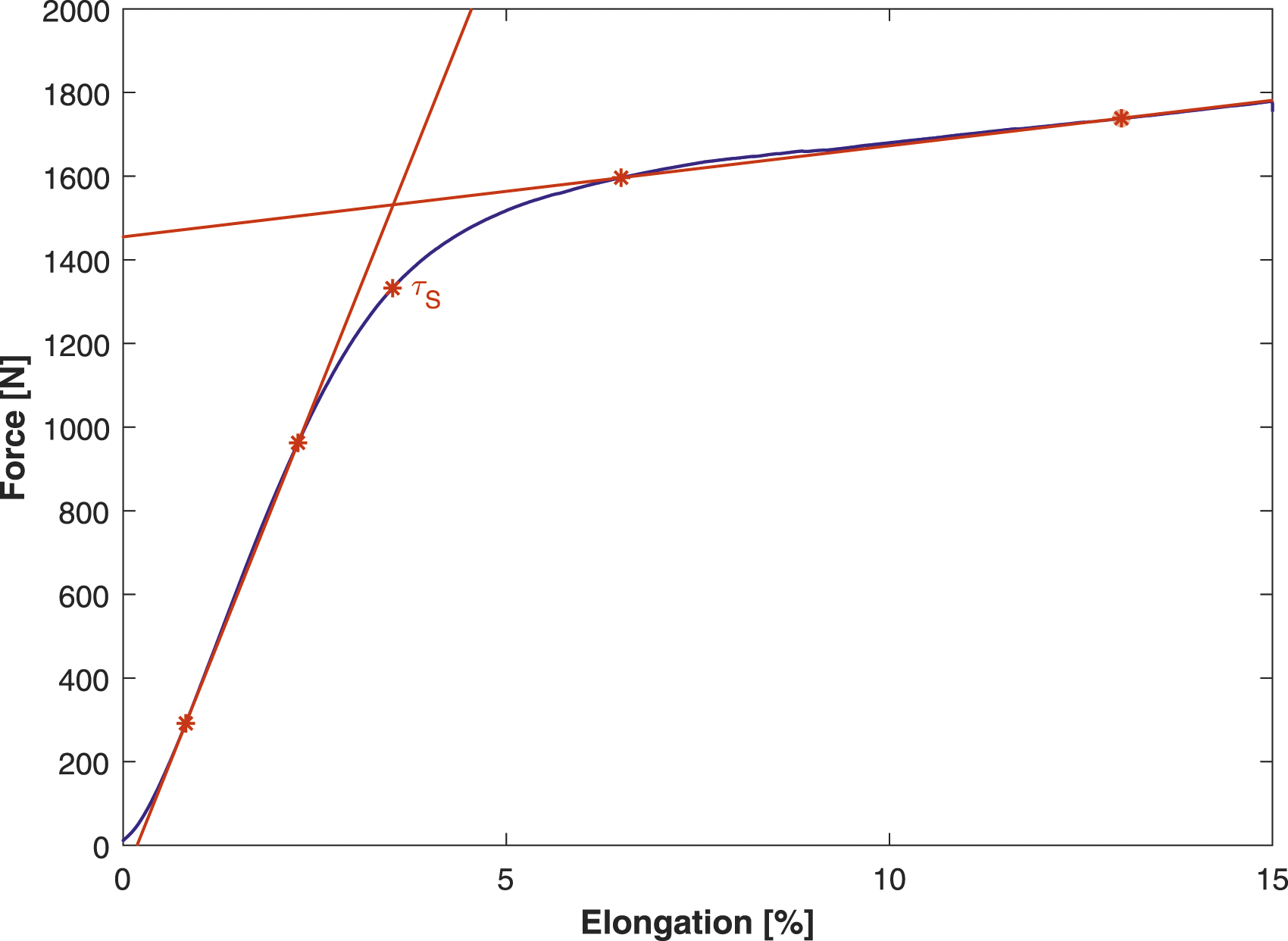
Example evaluation ILSS for
For the variation of the temperature set point, the highest values for
Perpendicular tensile strength
Perpendicular tensile strength results.

Furthermore, variation of the layup velocity shows that the overall highest tensile strength of 37.4 MPa was reached with a medium layup velocity of 1.5 m/min with a standard deviation of 3.9 MPa. However, considering the standard deviation, this value is on the same level as values generated at 7.5 m/min. Specimens placed at 4.5 m/min have similar strength with a better standard deviation. This indicates a plateau in mechanical strength for lay-up speeds at this set point temperature before it drops for layup speeds of 15 m/min or higher. Higher layup velocities result in a severe drop in tensile strengths of 27.7 MPa and 13.2 MPa for 15 m/min and 24 m/min respectively. The standard deviation at increased layup speeds was measured at 4.3 MPa for 15 m/min and 2.3 MPa at 24 m/min.
Micrographs
The following micrographs exhibit the cross-sections of the UD-samples produced at different processing conditions. The images were produced with a Keyence VHX 5000 digital microscope on a VH-Z250T objective with ×250 magnification. An area of approximately 11 mm × 3 mm was scanned and automatically stitched to show an overall panorama. From these panoramas a representative section was chosen. In general, the 12 layers of each sample remain distinguishable to the human eye. Dark spots are associated to intra- and interlaminar voids.
Figure 4(a) shows the reference sample of a post-consolidated T-AFP laminate hot press molded according to the processing instructions by TORAY. The processing conditions are confidential; however, it may be stated that the material is obviously consolidated at far higher pressures, with a longer dwell time and at reduced cooling rates as compared to in-situ consolidation. Thus, the resulting sample thickness of 2020 μ m (or ∼168 μ m consolidate ply thickness) is significantly lower as compared to the other laminates. This sample is without visible voids. However, regions with low fiber content are to be found, especially at the interfaces between adjacent layers. The fiber-volume content thus varies noticeably. Micrographs cross sections CF/LM-PAEK (a) Hot press benchmark, (b) v
Thickness laminates.

The as-delivered tape shows a significant amount of intrinsic pores, thickness variation and frequently areas were fibers at the tow surface are not impregnated with matrix (Figure 5). As-delivered tape.
The input tape quality in term of thickness tolerances translates into local waviness that accumulates and shows at the sample surface. The same is true for dry areas at the tow surface which will lead to interlaminar voids as no flow of thermoplastic matrix across the interface is possible. Finally, intralaminar voids are merely compressed during the consolidation, i.e., as long as pressure is applied through the compaction roller. Hence, at increased processing velocities where through-thickness heating of the tape is limited the voids and pores of the as-delivered tow material remain largely unaffected as matrix flow is limited. This effect is especially visible on the sample produced at 24 m/min were the amount of pores is noticeably higher compared to the samples produced at lower speeds.
Differential scanning calorimetry
DSC results.

At a constant processing velocity of 7.5 m/min a maximum crystallinity of 14.8% is reached at the highest temperature of 525°C. This may be attributed to the fact, that crystallization is promoted with laminate temperatures being above 220°C comparably longest during cool down (see green temperature curve Figure 2). Varying the processing velocity from 1.5 m/min to 24 m/min and keeping the processing temperature constant at 500°C shows no trend in the degree of crystallinity, with an average of 10.9 ± 0.7 over all five process speeds.
Averaging all specimen, a maximum, and reference crystallinity of approximately 24.5% with a standard deviation of 1.0% is reached after the samples are heated and cooled again.
Discussion
The results show that perpendicular tensile and interlaminar shear strength are on a comparable level for process speeds below 7.5 m/min at a set-point temperature of 500°C measured by the infrared camera of the layup end-effector. This plateau drops significantly for higher processing speeds. This was especially severe in the results of the perpendicular tensile strength. The operational set point translates into temperatures measured with thermocouples of 330°C at the nip point right in front of the compaction roller and 294°C behind it. Cool down beneath the consolidation roller to below the melting point of the material is thus achieved.
With these parameters a knock-down to 67% in ILSS and 43% in tensile strength were found compared to the hot pressed benchmark laminate. The mechanical performance values decrease with higher layup speeds. ILSS testing - the standard designed for thermoset composites - renders failure modes typical to the more ductile thermoplastic matrix composite. According to the norm, the values can thus only be used for comparison within this dedicated test series. Laminate quality, inspected via microsections, identified voids in interlaminar regions. A comparison with the as-delivered prepreg material showed that the tape surface is partially dry, i.e., withouth sufficient matrix to cover the single fibers. These dry areas cannot be filled during the highly transient process of in-situ consolidation where matrix flow is limited. Conclusively, areas of low interlaminar bond strength will occur with the investigated tape. It must be noted, that the material itself is still under development at TORAY. With an increase in material readiness level we expect significant improvements of the overall laminate quality. The consolidated ply thickness (CPT) correlates negatively with mechanical properties of the test specimen - the lowest thickness giving highest mechanical results - and may thus serve as an indicator for the degree of consolidation. For the samples produced at high processing speeds and higher set temperature the CPT can be attributed to the fact, that laminate temperatures just behind the compactation roller are higher which may favor deconsolidation and swelling of pores.
The reached crystallinities indicate a certain independence of the cooling rate within the described processing window, where the tows are quenched from just below the melt temperature to room temperature. Thus for placement speeds of 7.5 m/s and set temperatures of 500°C a crystallinity of 11.8% is reached, i.e., approximately 48% of samples cooled at moderate rates of 10 K/min in the DSC. In order to increase the crystallinity in in-situ consolidation, one may use a heated tooling of 150°C to 200°C to reduce quenching and promote secondary crystallization. It should be noted, however, that such heating has major implication on tooling designs and recurring costs during large scale production.
The overall approach of identifying machine independent, process parameters was successful. With this work we have determined a processing window for in-situ consolidation of LM-PAEK. Additionally, the temperatures measured on the laminate during the process are plausible with the determined mechanical performance of the laminates.
Conclusion
Within the examined process window for the carbon fiber-reinforced LM-PAEK the highest mechanical values were reached for placement speeds equal or below of 7.5 m/min and a nip point set temperature of 500°C, which corresponds to 330°C measured with the thermocouples. With regards to production a fast layup is favorable and thus the optimum for this process. Identifying and optimizing process parameters for in-situ consolidation via thermocouples demonstrated to be a sensible approach to configure the T-AFP process for a new LM-PAEK prepreg material. An advantage of this approach is the profound insight into the thermal history of the processed tows. Further, this approach is independent of the placement equipment used and especially the measurement inaccuracy given by the infrared cameras which allows for improved portability between different machines.
The T-AFP in-situ process showed its sensibility to as-delivered prepreg quality. With the material used in this work, which is not optimized for the in-situ process, we find significant knock-downs for the mechanical properties determined by ILSS and transverse tensile strength when compared to hot press consolidated reference samples. Further investigations will be conducted with tows of resin rich surface and lower fiber volume content to improve matrix flow at the interface between overlaid tapes which should improve interlaminar mechanical performance. In general, it would be beneficial to use the measured temperatures as an input for process simulation and final validation. With a virtual representation of in-situ consolidation usage of embedded sensors might be reduced to a minimum and instant process setup gets feasible.