
Abstract
Introduction
Mechatronic systems are engineered by using a wide range of disciplines and are collaborative in nature. Chen et al. 1 express that the collaborative development of mechatronic systems is error-prone because contemporary design environments do not allow adequate flow of design and manufacturing information across the domains.
The IDIOM framework presented by the authors2–4 facilitates design optimization of mechatronic systems in an early design phase to reduce time and cost consuming debugging and re-design in later design phases. Therefore, the presented method in IDIOM integrates engineering disciplines in a rather early design phase. The method uses a static dimensioning approach for the physical design of the component models as well as dynamic models to analyse behaviours of the entire system including maximum component loads. A genetic algorithm (GA) is employed to optimize the system in terms of size, energy and cost with respect to the developed models in the framework. The framework supports the addition of any relevant models for co-design optimization of mechatronic systems.
Figure 1 shows a typical system model in the proposed framework. The framework includes two kinds of component models: physical components and control components. The physical component models describe the classical mechanical components such as actuators, transmissions, and machine elements. Each physical component consists of three main sub-models including physical dimension, static properties and dynamic behaviour models to capture the characteristics of that component for later evaluation. The control component consists of two sub-models for implementing the control law and imposing control constraints on the system.

The structure of one physical and one control component in IDIOM.
An overview of IDIOM framework
The presented IDIOM software toolbox uses an object-oriented programming paradigm.
3
The component models are defined as class methods that represent objects in the optimization run. When the optimization begins, the software toolbox checks for errors and missing points of the configured system (sanity check). After this, dynamic and static preparation functions of the components are executed to determine the plant model and load the necessary data into the memory (details are presented in the ‘System model computation’ section). In this stage, a parallel pool and workers are employed to achieve the best use of a multi-core computer. The multi-objective function is evaluated and physical dimensions, static properties and dynamic behaviour models are executed. IDIOM can handle both single and multi-objective multidisciplinary design optimization problems and it also features a graphical user interface.
5
The basic concepts of the method in the IDIOM framework are as follows:
components, requirements as position profiles, a composition of the physical and control components composition results in a closed chain system composition ( each composition consists of one dynamic input port for a single-input single-output system and multi dynamic input ports for a multiple-input multiple-output (MIMO) system, each composition consists of interface connectors for open and closed loop dynamic configuration, and each composition includes input (
As shown in Figure 1, the physical component model (
A primary advantage of the original IDIOM framework is to avoid the direct computation of the timed sequence of system responses. The input signals are decomposed into harmonics by Fourier transform and the response of each harmonic is easily obtained from the system transfer function. With the extension presented in this paper, the IDIOM framework contains MIMO and non-linear components and hence the frequency decomposition method is not applicable. The sequence of system response is instead computed directly by the system state-update equation and the input sequences. In the application example of this paper, an optimal proportional–integral–derivative (PID) control method and user-defined control constraints are evaluated using simulation within the optimization evaluation. This has increased the computation time considerably in comparison with the previously presented Fourier-based system behaviour computation. However, the computational time is still on a reasonable level that allows the new methodology to be a valuable tool in the early-phase co-design optimization of mechatronic systems.
The outline of the paper is as follows, Section ‘Introduction’ is an introduction of related work and the contribution. Section ‘Review of related work’ is a literature review of previous studies. Section ‘Basics of the supported software framework’ presents the basics of the supported software framework together with detailed mathematical definitions of each concept and a conceptual case study is also presented to facilitate the comprehension of the definitions by
Review of related work
The use of multidisciplinary design optimization for dynamic system design is reviewed by Allison and Herber. 6 Li et al. 7 derived a general model to mathematically define the concurrent design of a mechatronic system. Based on this model, a concurrent engineering approach, design-for-control (DFC), is formally presented. In comparison with other mechatronic design methodologies, DFC highlights obtaining a dynamic model of the mechanical structure by a structural design and a careful selection of mechanical parameters. Once the simple dynamic model is available, regardless of the complexity of the mechanical structure, the controller design is achieved and better control performance is realized. Nevertheless, their method includes complex models as well as time-consuming iterations.
Gausemeier et al. 8 presented a graphical method to express the functional principle solution of a mechatronic system called the semi-formal specification language. They applied this method to a vehicle guidance system. A gradient-based framework is proposed by Lee et al. 9 for optimization of an aerodynamic system and the controller is designed using high-fidelity models. They have considered the system’s general properties such as time scales of the model and used cost function to reduce the computational task of fluid dynamic simulations. They reduced the optimization time by control of the error of gradient which is computed by the optimizer. They provided a few use cases that show their method is applicable for optimizing supersonic vehicle shapes and can handle both sharp and smooth geometry design parameters. However, their method does not cover the detailed physical design of systems.
Delbecq et al. 10 present a Python framework for the design of embedded mechatronic systems to support the designer in satisfying constraints such as energy consumption, influencing the environment, geometrical integration and reliability. The dynamic simulation through zero-dimensional to one-dimensional models of the system is used to validate the architectural choices. Their optimization approach cannot be applied to the system level even during the early design phases.
Dumlu 11 proposed a fractional-order adaptive integral sliding mode control scheme to perform a trajectory tracking control of six degrees of freedom (6-DOF) robotic manipulator. Their research is one out of a huge number of other studies that focuses on control of robotic systems where the component design and optimization are neglected.
Chhabra and Emami 12 used bond graphs and block diagrams to present a concurrent design method. They considered a mechatronic system as an energy system and applied the laws of thermodynamics to specify design criteria. Their paper studies the principles of a multidisciplinary system and the flow of energy and information throughout its different constituents. Subsequently, they introduced a fuzzy logic-based concurrent design framework where they applied it on a 5-DOF industrial robot manipulator. They used a holistic concurrent design approach to convert a multi-objective constrained optimization to a single-objective unconstrained problem. 13
Domingues et al.
14
present a design method to achieve size, efficiency, optimal driving performance and thermal characteristics of electric powertrain components. Their methodology finds optimal component combinations based on some requirements. The
An integrated design method called DFC, is proposed by Mohebbi et al. 15 for a quadrotor unmanned aerial vehicle (UAV) equipped with a stereo visual servoing system. They presented the dynamics and a control model of the quadrotor UAV and its visual servoing system, and later a design process was implemented in four iterations. Subsequently, Mohebbi et al. 16 proposed a multi-criteria approach for the conceptual design of mechatronic systems. They proposed three different methods using a case study of designing a vision-guided quadrotor drone system. Three different aggregation techniques were used in these methods such as Choquet integral, Sugeno integral and fuzzy-based neural network. They have concluded that even though the Sugeno fuzzy can be a useful aggregation function for decisions under uncertainty, but the approaches using Choquet fuzzy and fuzzy integral-based neural networks are more reliable and precise in achieving results for multi-criteria design problems. Choquet fuzzy integrals are one of the most reliable models which are used in decision theory for multi-criteria decision-making. However, the fuzzy measures have many parameters and are usually complex when only relying on the designer’s intuition. In another study, Mohebbi et al. 17 compared three methods of fuzzy measure identification tailored for a case study of designing a vision-guided quadrotor drone.
Subsequently, they proposed a fuzzy-based approach 18 for modelling a unified performance evaluation index in the detailed design phase for a vision-guided quadrotor unmanned aerial vehicle. This performance index is a multidisciplinary objective function that collects all the design requirements from different disciplines and considers the interactions between the objectives and implemented particle swarm optimization algorithm. Their method is a systematic and multi-objective design thinking approach rather than a sequential design method, however, they have used unnecessary complex methods and did not consider integrate physical dimensioning, dynamic behaviour and static properties of the systems in an early phases of design.
Previously mentioned IDIOM framework is a well-developed framework to fill the existing methodology gaps when treating different engineering disciplines in the co-design of mechatronic systems. 19 IDIOM is capable of dealing with both single and multi-objective multidisciplinary problems. An early-phase co-design method is implemented in IDIOM which can handle multi-DOF linear and non-linear mechatronic systems and yield an optimum solution with respect to defined objective(s) and constraint(s). Physical dimensioning, dynamic behaviour and static properties are considered and models which are simple enough while capturing the main characteristics of the systems are considered. Individual component models are developed throughout the method in IDIOM which allows configuration of system concepts, therefore any system which uses the available developed components is realizable by the method. However, there is yet no formal systematic definition of this framework and its tools. This paper presents formal definitions of the modelling artefacts and methodology of the IDIOM framework. The rigorous and unambiguous descriptions facilitate understanding of the architecture and capabilities of the IDIOM framework and are helpful for software implementation to support the IDIOM framework. The formal definitions, including all modelling artefacts and the computation procedure, facilitate comprehension and software implementation of the framework. Moreover, the modelling capability of the IDIOM framework is enhanced by adding non-linear mechatronic components, for example, a 2-DOFarm. Further, an optimal control component, namely a PID controller is added as a new component model.
Basics of the supported software framework
This section presents formal definitions of all model components of the framework. To assist the reader, the case study in Figure 2 is used to illustrate abstract concepts throughout the paper.

The structure of a two-degrees-of-freedom (2-DOF) robot arm (
The case study consists of four physical components (

System configuration in IDIOM framework for static analysis.
Let
For the case study in Figure 2, the desired path of the load component is illustrated in Figure 4, which is a two-dimensional trajectory, hence,

Defined output path for the system.
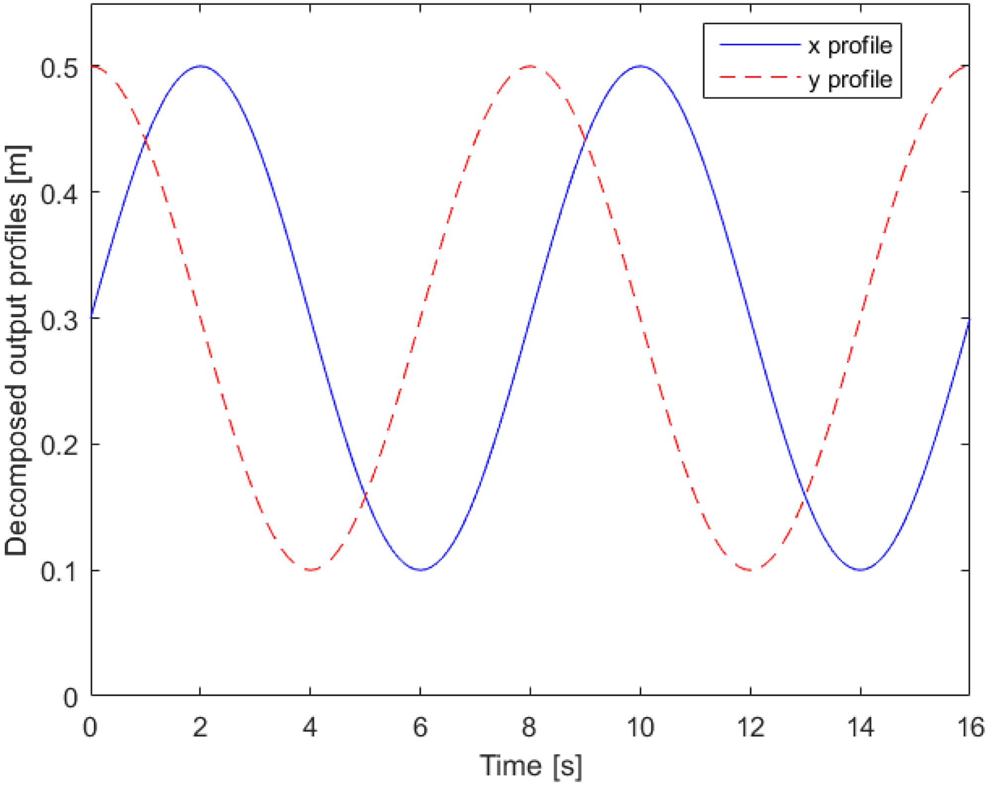
Decomposed output path for the system.
A functional DOF of a component is the translational or rotational axis, denoted as
An input/output port is a set of timed signals (

As shown in Figure 3, each component model in the case study has input and output ports but there is no component connected to the input ports of DC motors, so the input port sets for these components are empty. The 2-DOF arm is treated as one component which has two input ports and two output ports. Table 1 depicts the detailed information of the input and output ports of each component.
Input,

In Table 1,
If no external force is applied to the load, then the output force signals of the load are constant 0.
Component level concept
Physical component
The physical dimension (
An actuator component is a physical component that provides energy/power/torque to the mechanical system and carries the control signal. Let
(Load component)
The load component is the last component (
(Structural component)
The structural component is a physical component that carries the load and transforms position/torque. Some examples of structural components are robotic arms, transmissions and mechanical springs.
(Design parameter)
Design parameters of the physical component model 

Table 2 lists all design parameters of all components of the case study except the material properties of components, which are derived by considering steel material.
Design parameters.

Design parameters.
The design variables (


The design variables (
Design variables and defined ranges.

A physical design constraint (
The physical constraints include the speed limit, peak torque, root-mean-square (RMS) torque and stress of that component model, which are defined in the physical dimension (
The design answers (


Table 4 shows the design answers for each component for the case study.
Design answers.

The physical dimension (
The physical dimension (
1) DC motors:

3) Load component:
The geometrical specifications of the load component are defined by the user. Hence, it includes no
The static load transfer model (

1) DC motors 1 and 2:
The static load transfer of a component model is applied to its functional DOF. In the case study, both DC motors are fixed statically to an inertial frame, and there is no need for the static load transformation model to be executed since there is no other component defined on the input side of the DC motors. Hence, the input port sets of the two motors are both empty, as illustrated in Table 1.
2) 2-DOF arm:
Static load transfer of the 2-DOF arm is dependent on the design variables (

The load component is a mass (
The dynamic behaviour model (
Note that the dynamic behaviour of the physical components are described by ordinary differential equations (ODEs). Differential algebraic equations are the interface equations used to configure dynamics in the system modelling and composed system models are as well ODEs. However, stochastic differential equations are not considered in the approach.
(Flexible component)
A flexible component composed of two mass/inertia bodies with a constitutive relation. The constitutive relation is an equation that models a subsystem of spring(s) and damper(s).
(Rigid component)
A rigid component is just one inertia/mass body. For a rotational body, the inertia is defined in relation to
This example distinguishes rigid, flexible and actuator components’ dynamics.
1) Flexible component:
A flexible component consists of two mass/inertia bodies connected by a spring (


Flexible component.
2) Rigid component:
A rigid component is one mass/inertia and possibly a transmission between the input and output signals as shown in Figure 7 for the translational case.
Rigid component.
The dynamics of the rigid body is given in (7):
A revolute actuator component as illustrated in Def. 3 has dynamic as given in (8) and (9):

The detailed expressions related to the dynamic behaviour model and the implemented control method of the case study are described in the ‘Case study’ section.
Control component
A control component (
A sensor component is defined to sense and measure the output variable of a specific physical component. Let (
(Control component)
The control component represents a control method that is designed to minimize the difference between the desired output profile and actual system output for a particular implementation.
To design the control component, the open-loop plant model must be derived. In this work, the open-loop model is obtained symbolically by Wolfram Mathematica solver. The plant model may be linear or non-linear. In the latter case, the non-linear model can be linearized by the mentioned solver. The detailed approach is represented in Algorithm 1.
For the case study, PID control is implemented on the two DOF arms, separately for each degree of freedom, and thus we have six control design parameters of
The control performance constraint (
Root mean integrated square error (
In the case study, the 2-DOF arm is defined as a sensor component, 

Dynamic system modelling
For dynamic system modelling, the physical and control components are connected into a graph called the IDIOM model.
The IDIOM model (
Each edge is an IDIOM connector which is normally an arrow. There is an arrow between the objects 

Given a set of physical components
Given a composition
(ii)
hence, numerical evaluation of
Figure 8 shows the open-chain component composition of a system in IDIOM. Currently, the delimitation of the framework is that it only handles systems composed as open-chain configurations unless a control component is included.

Two system compositions of components.
The component models
We use the case study shown in Figure 2 as an example of how an IDIOM model
1) DC motor 1 and 2-DOF arm


Optimization
The IDIOM objective function (


The objective functions are based on pre-specified component cost functions (e.g., mass, cost, and energy loss) and each function in each component model may have multiple outputs and they together form
With the given physical constraints, the control performance constraints 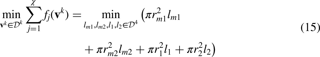
Control design variables.

An integrated control and physical design optimization approach is used in the IDIOM framework to emphasize the interdependent relation between physical and dynamic design. The optimizer implemented in the IDIOM framework is a genetic algorithm (GA). GA is chosen since it can handle problems with discrete design variables and is implementable on problems with non-linear objectives. GA is an approach to solve both constrained and unconstrained problems and can be applied to a diverse range of complex problems. To use other optimization algorithms with the method, the corresponding algorithm should be integrated into the method and implemented to the IDIOM framework. The purpose of holistic design optimization is to achieve the best overall system properties rather than design optimization of each component independently. Static properties, physical limitations and control constraints are evaluated concurrently by the optimization solver, where the ‘physical dimension’ models are also calculated. In previous work by Frede et al., 2 the use of multiple optimization criteria is enabled. Maximum generation number and population size are to be defined by the user, if not; the default values are 200 and 40, respectively.
System model computation
The mechatronic system concept is configured using a physical and dynamic component library based on detailed specifications from the user. The methodology implemented in the framework with all the constituent components and models is shown in Figure 9. The system concept is generated by drag and drop of physical and control components from the component library of the framework. After having a decision on a system configuration and requirements in terms of load specification, required dynamic performance and optimization objectives, the system is optimized according to Algorithms 1 to 3. It should be noted that all the system models implemented in the framework so far, including the required motion profiles, are continuous time.

Overview of the methodology.
For an arbitrary system composition with
The inputs for Algorithm 1 are the system concept as a graph (
The algorithm is executed in the chain between the two specified physical components as
One solution to solve symbolic algebraic differential equations is to use the software Wolfram Mathematica. In lines 11 to 13 in Algorithm 1, the Mathematica kernel is started and the symbolic 

According to Algorithm 1 and Definition 18, for an arbitrary IDIOM model composition of
According to Algorithm 1, the dynamic system composition in the IDIOM framework is provable, so it is complete. □
Algorithm 2 uses physical dimension (
The inputs for Algorithm 1 are the system concept in a graph (
In lines 1–3, the load component’s (
In the next step, in line 4, a loop starts to go through the components from output to input side for the algorithm to execute the physical dimension (

Algorithm 3 checks for the satisfaction of the control constraints (

Given a composition of components as an IDIOM model (Definition 18), using the method presented in Algorithms 1 to 3 there is a consistent optimization solution independent of the solver, if and only if
Case study
Physical design constraints
The physical design constraints (Definition 8) of each case study components (Figure 2) are as follows:
1) Physical constraints on the motor model:
The physical design constraints of the two DC motors are adopted from scaling approaches presented by Roos et al.,22,23 which specify the relationship between the rated torque and the actual RMS torque as in (17):


The constraint on the 2-DOF arm is that the strength of the two arms is larger than the required force. The equation is derived from Hamrock et al.
24
:

Forces affecting the 2-DOF arm and the max values of them.
Static load transformation
1)
There is no need to execute
2)
The
The angular positions of the arms are derived from inverse kinematics.
25
For the angular position of the second arm (


The Lagrangian of the robot arm is taken from Efe 27 and Mahil and Al-Durra, 28 which are used to evaluate system dynamics.
Later in the design,

Torques and their maximum values on the DC motors.
3) 


Dynamic behaviour model
The detailed
1) DC motor:
For both of the DC motors we have
2) 2-DOF arm:
We employ Lagrangian mechanics27,28 to evaluate the dynamic differential equations.
3) Load:
The load component’s dynamics is approximated by a point mass whose dynamics at the
For evaluating the system dynamics, two PID controllers are employed on the 2-DOF arm, where the currents 


By substituting (41) in (40), we obtain
Results and discussion
Using an optimal PID control, the required trajectory tracking performance is achieved and the optimal system is designed. The result of the optimization for two design problems is presented and compared in Table 6 where we altered only the control constraints boundaries in problems 1 and 2 to check the effect of the constraint on the physical design of the system. The boundaries for the control constraints of 

Optimization output.

Problem 2:


Trajectory tracking of the first arm (first motor angular position).

Trajectory tracking of the second arm (second motor angular position).

Error of trajectory tracking by the first and second manipulators.

Trajectory tracking by the end effector.
These figures are derived from the optimal design of the system in problem 1 and show the accurate performance of the optimal PID control for the tracking of the angles of the arms and a well-performed reference position tracking of the end effector using the controlled angles. The computational time for a population size of 25 and the generation of 40 using GA is 8864.58 s which is a reasonable time for an integrated design optimization and control of mechatronic systems with 10 optimization variables; including four physical design variables and six control design variables.
In problems 1 and 2 as shown in Table 6, the entire system is optimized with GA for the objective of minimizing the volume with respect to some physical constraints (explained in Definition 8 illustrative example and in the ‘Dynamic behavioural model’ section) as well as control constraints (
The results in Table 6 show the large effect of the control constraints on the physical design. In problem 2, the control constraints’ boundaries are larger than the ones in problem 1, which leads to a larger physical design space solution and at the end the optimal physical design values and objective function (volume) are better in problem 2 than problem 1.
Problem 1:
Problem 2:
ElKhateeb and Badr
30
studied the same case study without any physical design and dimensioning and only six control parameters are defined as optimization variables and the objective of the Bee colony algorithm optimization is defined to be mean absolute error (MAE). For comparison purposes, we select the same control parameters to range as presented by ElKhateeb and Badr
30
and we define the control constraint to be 
Comparison results.

Conclusion
Formal definitions of the proposed algorithm in the IDIOM (Integrated Design and Optimization of Mechatronic Systems) framework are presented in this paper to assist the conception of the rigorous and unambiguous definitions of the framework. The modelling capability of the IDIOM framework is improved by adding a highly non-linear complex mechatronic component as a 2-DOF arm and a new type of control component, namely an optimal PID controller. A case study is implemented and tested using the Lagrange dynamic equations for the 2- DOF arm system. The optimal PID control is implemented in the supported software framework to control each arm separately and get trajectory tracking results in the end effector of the 2-DOF arm. The system is optimized for volume and the results are compared to the achieved results of the optimal PID control using a Bee colony method which shows preciseness and satisfaction of trajectory tracking of the arms and end effector in our method. The paper covers a few technological fields such as modelling, optimization, physical design and control. The optimization is advanced to solve multidisciplinary problems where engineering features of systems from different domains are considered. The method allows simultaneous integration of mechanical, electrical and control domains. For the multidisciplinary design, different constraints with respect to the objectives and involved domains are added to the method.
The method is complete in a sense of covering physical dimension, dynamic evaluation and static properties of the system and it proves competitiveness of the control constraints results although including the physical design and constraints of the system impose solution limitations. Regarding the scalability of the proposed method and for the method to be as holistic as possible, all design parameters are required to be free variables, which would be unrealistic even for a small number of components due to the course of dimensionality. 31 This is also true for a large number of components. A good future step would be to include design philosophies such as cooperation, agile, information management, data exchange and networking. 32 To integrate these iterative methods with the presented method in this paper, the optimization has to be run in each iteration separately or another solution would be to implement a two-loop optimization for detailed and holistic design, respectively. However, this has to be reanalysed in detail to realize the best possible solution. To deal with incomplete information in the early stages of design, in the detailed design method in this paper static transformation models are used to derive an initial system model. A similar model/method can be considered to define initial input parameters and attributes in the holistic design loop. Even though the IDIOM framework facilitates an early-phase co-design optimization of mechatronic systems, another good future step would be to apply the presented method on a designed prototype and examine the feasibility of solution in the real world with real limitations. One another extension to the method would be to include embedded control implementation aspects in the design. 33