
Abstract
Introduction
Sandwich structures are usually composed of a low-density core material and thin, hard upper and lower face plates. This lightweight structure provides high bending stiffness, good energy absorption and impact resistance properties. Therefore, sandwich structures are widely used in engineering applications as typical lightweight, high-strength structures. Sandwich structure plate are primarily subjected to tension and compression. The core layers of these face plates are primarily subjected to compression and shear. Current studies on sandwich structures mainly focus on bending properties,1–6 compressive properties,7–12 and energy absorption properties.13–20
The basic form of the sandwich structure currently used in engineering applications consists of two thin, strong face plates and a lightweight core material that is filled between the face plates and firmly connected to them. There are many materials used for the face plates, such as aluminum, stainless steel, composite laminates etc. In terms of the core material, there are foam sandwich structures,21–24 honeycomb sandwich structures,25–30 corrugated sandwich structures31–37 and grid sandwich structures.38–43 There is a large amount of literature on sandwich structures; moreover, carbon fibers are typical lightweight, high-strength fibers. Therefore, due to space limitations, this paper reviews only the static mechanical properties of sandwich structures that utilize carbon fibers for the panel or core or entire sandwich plate. Even within these constraints, in the smaller field of the static properties of carbon fiber sandwich structures, many scholars have already studied the mechanical properties of sandwich structures. Petras and Zhu44,45 constructed a failure mode diagram of a honeycomb-core sandwich structure under three-point bending and quasi static indentation and studied the factors affecting the interfacial failure mode and the corresponding failure load. Kaman 46 studied the influence of honeycomb size, core layer density, core layer material, and panel thickness on the damage properties of honeycomb sandwich plates. Goswami and Becker 47 investigated delamination cracks along the panel/core interface of sandwich structures under lateral loads. Fan 48 performed out-of-plane compression, in-plane compression and three-point bending experiments of sandwich structures with grid cores, foam cores, and honeycomb cores. Russell 49 used carbon fiber composite materials to design and manufacture a square honeycomb sandwich structure; the author measured the changes in the out-of-plane compression and in-plane shear responses of this structure with respect to the relative density. Yin et al. 50 studied the mechanical properties of honeycombs reinforced by hollow lattice trusses. During static tests of sandwich structures, delamination often occurs between the surface and the core layer. For this reason, many researchers have investigated methods to strengthen the bond between the surface layer and the core layer, including integrated sandwich plates preparation techniques, stitching techniques, and methods to increase the bonding area.51–53 The dynamic performance of sandwich face plates is similar to the static performance. For example, the lower panel and core layer are easy to debonding and are damaged under an impact load.
This paper mainly reviews the current research status of carbon fiber sandwich structures with grid cores, truss cores, and foam cores in terms of their bending properties, compressive properties, and failure morphologies; moreover, this paper notes some problems in the current research in this field. The lightweight, high-strength, three-dimensional structure of a beetle forewing was used as a model, which can provide a method to solve the problems and can offer an idea for the research and development of a new generation of composite sandwich boards reinforced with carbon fibers, basalt fibers, or other fibers.
Core structure types and bending properties of carbon fiber-reinforced sandwich plates
According to the currently published literature, sandwich structures are divided into three categories in this paper: grid core, truss core, and foam core. The research status of the bending properties of these structures is described below.
Grid-core sandwich plates
The grid-core sandwich structure refers to a sandwich panel whose core layer is composed of regular small grids, for which the core layer shapes include a triangular grid core (Figure 1), a square honeycomb core, and a grid-reinforced honeycomb core (Figure 2(c)). The core layer materials are mainly aluminum and carbon fibers. Researchers have extensively investigated the bending properties of these structures and have reached some valuable conclusions. For example, Russell et al.
54
conducted a bending test on a composite structure with a woven carbon fiber square honeycomb core and a carbon fiber surface layer. The failure modes of simply supported and clamped beams under three-point bending were systematically studied, and the main failure was found, which included face micro buckling, surface wrinkling, core shear and indentation (Figure 3). Wang et al.
55
conducted a three-point bending experiment on a sandwich structure composed of an aluminum honeycomb core and carbon fiber surface and found that the strength and stiffness of the sandwich structure can be significantly improved by increasing the density of the honeycomb core. Fan et al.
56
conducted an experiment of carbon fiber reinforced Kagome lattice grids. They found that high specific strength and specific stiffness can be achieved in comparison with other cellular materials, rendering the carbon fiber reinforced grids weight efficient. In addition, debonding is the main weakness of the carbon fiber reinforced sandwich plates. Xiong et al.
57
prepared carbon fiber composite sandwich plates with egg and pyramidal honeycomb cores using the interlocking method. Three point bending tests were carried out, and the result showed that face wrinkling and debonding occurred. Liu et al.
58
conducted three-point bending tests to investigate mechanical behavior of the Y-frame sandwich core. The results showed that the relative density has a great impact on the value of load-displacement curves and bending failure load. Xu et al.
59
prepared a triangular grid-core sandwich structure using T700 carbon fibers and epoxy resin (Figure 1), which they used to perform experiments and finite element simulation studies. The failures that occurred in these structures during the tests were mainly panel yield and core shear failure. The end of the panel yielded in Xu’s test, whereas in the test conducted by Russell et al.,
49
the middle of the panel yielded. According to our analysis, from a theoretical perspective, in the case of a downward bending load, the compressive stress is the largest in the middle of the upper panel, and buckling should occur in this position. However, since the sandwich panel is formed by bonding the panel and the core layer, the location where the bonding between the panel and the core layer is uneven, and it is easy to debonding. After debonding, the panel is in a compressed state at the debonding locations. Because the panel is thin, it easily buckles and is damaged. Accordingly, we guess that it may have had poor adhesion at the end of the panel in Xu’s test, which may have led to buckling of the end of the panel.
59
Sugiyama et al.
60
manufactured four integrated sandwich structures with honeycomb, rhombus, rectangle and circle shapes based on 3D printing technology and continuous carbon fiber. The three-point bending test showed that the maximum load and bending modulus of different core shapes increase with the increase of effective density, but the sandwich structure with rhombus core was the strongest. Han et al.
61
fabricated a novel sandwich honeycomb structure (DSH) based on the periodic region of mantis shrimp’s dactyl club using unidirectional carbon fiber and aluminum honeycomb materials. The bending test showed that the quasi-isotropic spiral arrangement of carbon fibers is an effective way to improve the bending energy absorption of DSH. Triangular grid core
59
: (a) A sample, (b) A single honeycomb size, and (c) a single triangular core size (note that (b–c) have been redrawn according to the original images). Three aluminum honeycomb forms toughened by Kevlar fibers
63
: (a) Aluminum honeycomb, (b) Orthogonal aluminum grid, and (c) Honeycomb-filled aluminum grid. Schematic diagrams of the four main failure modes
55
: (a) Microbuckling failure of the surface layer, (b) Shear failure of the core layer, (c) Indentation, and (d) Wrinkling damage of the surface layer.
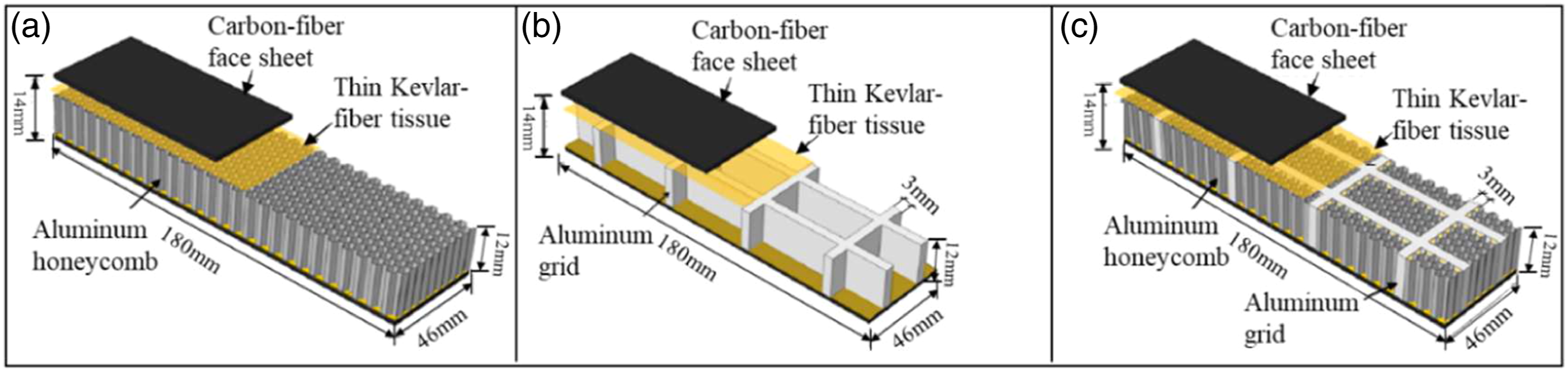

In view of the debonding between the surface layer and the core layer that often occurs in bending tests, Shi et al. 62 studied the carbon fiber-aluminum honeycomb-core sandwich structure using Kevlar fiber toughening. The specific toughening method is as follows: first, impregnate the carbon fiber fabric with epoxy resin, and then superimpose the layers of carbon fibers; second, physically disperse the 12-mm-long cut Kevlar fiber bundle to form a thin Kevlar layer (shown in yellow in Figure 2); finally, the thin Kevlar fibrous tissue is placed on the surface of the wet carbon fiber. This toughening method delays the occurrence of debonding failure at the panel/core interface without substantially increasing the structural weight. Moreover, the three-point bending test showed that the peak load of the samples with Kevlar fiber toughening was approximately 14% higher than that of the untoughened test samples. Accordingly, Shi et al. 63 also prepared honeycomb-carbon fiber panel sandwich structures with different core layers: orthogonal aluminum grids, aluminum honeycombs, and orthogonal aluminum grids filled with aluminum honeycombs, as shown in Figure 2. The panel/core interface of the three types of structures is toughened with Kevlar fibers (the toughening method is the same as the toughening method described above). On average, the peak bending load and energy absorption capacity of the honeycomb-filled grid-core sandwich structure are increased by 14% and 62%, respectively, after Kevlar fiber toughening. This finding indicates that the thin aramid fiber structure effectively inhibits interfacial delamination. Chen et al. 64 studied the properties of the carbon fiber sandwich structure toughened by short fibers and found that short aramid fibers can inhibit interfacial cracking and subsequent crack propagation in the carbon fiber sandwich structure during three-point bending, thereby significantly improving the mechanical properties. In addition, their experimental results showed that the structure toughened with short aramid fibers exhibited substantially increased ultimate load and energy absorption properties while slightly increasing the structural weight compared with untoughened structures.
Truss-core sandwich plate
The sandwich structure with a truss core is composed of various trusses. In this structure, the core layer shapes include pyramids, two-dimensional trusses (Figure 4(b)), X-trusses and Y-trusses. Many scholars have investigated the bending properties of truss-core sandwich structures and have obtained valuable findings. George et al.
65
carried out an experimental study of carbon fiber sandwich structures with pyramidal cores and found that the shear strength and modulus of the structures with carbon fiber pyramidal cores (Figure 4) and honeycomb cores were similar. However, the sample experienced delamination failure between the surface layer and the core layer during testing, preventing the structure from exhibiting its full potential. Usually, the peak stress occurred at the position of nodal fracture rather than at the position of the truss member fracture. This phenomenon also indicated that the buckling and crushing of the truss members occurred in the elastic stage and that the stress at the buckling position did not reach the yield strength of the material during the buckling failure. Xu et al.
66
carried out an experimental study of carbon fiber sandwich structures with pyramidal cores and found that the failure modes of the sandwich beams mainly depend on their geometry parameters. Namely, the main failure mode of the beam with thin face plates and strong structs is face plates wrinkling. But that with thick face plates or weak structs tends to core member buckling. Wang et al.
67
used the hot-pressing method to produce carbon fiber-reinforced polymer (CFRP) composite sandwich plates with a 2-D lattice truss core from unidirectional carbon/epoxy prepregs. The two-dimensional truss core consisted of several trusses that were parallel to each other, as shown in Figure 4(b). By studying the bending and shear properties of this structure, they found that the main disadvantage was delamination in the panel itself (Figure 4(c)); delamination always occurred in the area where the truss element was embedded in the panel. In addition, the shear strength of this structure was higher than the interfacial strength of the panel. The abovementioned studies show that the interface between the core layer and the panel and the interface between laminated panel layers are the weakest positions of the entire structure. These positions are prone to debonding.
Foam-core sandwich plates
At present, the cores of foam-core sandwich structures are mainly metal foams and polymer foams. Aluminum foam has attracted widespread attention due to its technical advantages and comprehensive performance.68,69 This paper only studies the research progress of foam sandwich plates where the panel consists of carbon fibers. Pandey et al.
70
investigated the bending performance of sandwich panel with aluminium hybrid foam (HF) core and carbon fiber surface layer. The research showed that the flexural bearing capacity of sandwich structure was 8 times higher than that of bare foam structure, while the flexural stiffness of sandwich structure was 9 times higher than that of bare foam structure, and the energy absorption was 58% higher than that of bare foam structure. Bragagnolo et al.
71
investigated the influence of three core materials with different cell characteristics on the interface strength of foam core and CFRP skin through mechanical testing and numerical modelling. It was found that foams with coarser pore structure were favorable for higher resin absorption at the interface during manufacturing, which resulted in stronger interfacial bonding between foams and CFRP. Selver et al.
72
investigated the flexural properties of carbon fiber z needle inserted into extruded polystyrene foam core. The results showed that the flexural load, strength and modulus of carbon fiber sandwich composite were significantly increased after the insertion of Carbon fiber Z needle. Zhang et al.
73
inserted Z-pinned carbon fibers into the foam core to form a new X-truss/foam sandwich structure; they studied the mechanical properties of this new structure. Their study showed that the insertion angle ω (shown in Figure 5) and volume fraction of the Z-pinned carbon fibers are the most important structural parameters. As the Z-pin insertion angle increases, the Compression properties improves, whereas the shear and bending strength decreases. In the tests, the best shear and bending performance was observed when the Z-pin insertion angle was 45°, whereas the best Compression properties was observed when the Z-pin insertion angle was 90°. In addition, in the flat compression tests, the foam core was used as an elastic foundation to prevent buckling in the Z-pinned carbon fiber. Thus, the final compressive stress was higher than the sum of the respective contributions of the foam core and the Z-pinned carbon fibers. Sun et al.
74
studied the interfacial toughness and toughening mechanism of a sandwich beam composed of a double-sided carbon fiber/epoxy composite layer and an aluminum foam-core layer. During the manufacturing process of the sandwich beam, short aramid fibers with different lengths (6–14 mm, spaced 2 mm apart) and densities (12 g/m2) were inserted at the sandwich beam panel/core interface. Through double cantilever beam tests, the toughness of the panel/core interface of different design schemes for the sandwich beam was tested. The test results showed that the interface toughening was improved to varying degrees after toughening with short aramid fibers. Scanning electron microscopy analyses showed that the contact area between short fibers (6 mm in length) and aluminum foam was larger than that between long fibers and aluminum foam, which confirmed the importance of increasing the contact area between the aramid fibers and the uneven surface of aluminum foam. Yan et al.
75
prepared sandwich beams composed of carbon fiber face plates, which were prepared with E44 epoxy resin and 650 resin curing agent, and an aluminum foam-core layer, and they studied the effect of the aluminum foam density on the properties of these beams (Figure 6(a)). Figure 6 shows that when the foam-core density was 0.49 g/cm3 and 0.60 g/cm3, the growth rates of the peak load were 24.0% and 28.9%, respectively. However, when the foam-core density was increased to 0.73 g/cm3, the peak load increase was not as large as that in the other two cases, and the maximum increase was 19.0%. Note that when the carbon fiber fabric was 5 layers, the peak load value decreased when the foam-core density increased from 0.60 g/cm3 to 0.73 g/cm3. This finding shows that to obtain the desired strength, a certain balance is needed between the density of the foam core and the number of carbon fiber layers. In this study, the peak load value was the highest when the foam-core density was 0.60 g/cm3 and the number of carbon fiber fabric layers was 5. In addition, three failure modes were found in the test (as shown in Figure 6(b)–(d)). The three failure modes were related to the strength of the sandwich structure. When the density of the foamed aluminum core layer was low and there were few carbon fiber layers in the panel, the primary failure mode was shear failure of the core layer. In contrast, debonding failure was the primary failure mode when the sandwich structure had a higher peak load and stiffness. When the peak load occurred earlier, the peak load was higher, and debonding occurred earlier. In view of the debonding between the surface layer and the core layer that often occurs in bending tests, Sun et al.
76
inserted short aramid fibers of different lengths and densities into the face–core interface during the sandwich fabrication process. Under the three-point bending condition, the peak load increased by 38% and the energy absorption increased by nearly 80%. The weight percentage of the aramid fiber was less than 1% of the total weight of the sandwich structure, which shows the short aramid fiber interweaving is effective in both cost and structural performance. To further improve the enhancement effect of aramid fiber - fiber reinforced adhesive joint, Sun et al.
77
conducted ultrasonic treatment on aramid fiber to different surface conditions. To study the effect of surface treatment on the aramid fiber, Critical energy release rate of the carbonfiber/aluminum foam sandwich beams with as received and treated interfacial aramid fibers were measured. The results showed that the critical energy release rate of the treated aramid fiber is enhanced under the condition of double cantilever beam. The interfacial properties of aramid fibers under different surface conditions were studied and discussed by scanning electron microscopy. The results showed that the aramid fiber and epoxy resin are highly bonded after surface treatment, which absorbs more energy through fiber bridge during crack opening and propagation. Long et al.
78
conducted a three-point bending test on a foam-core sandwich panel toughened with Z-pinned carbon fibers (Figure 5) and found that the method of using Z-pinned carbon fibers to strengthen the polymer foam-core material was successful. The connection force between the surface layer and the core layer was increased by the Z-pinned carbon fibers, which significantly improved the collapse resistance of the foam-core material under bending. Sun et al.
79
studied the interface toughness and toughening mechanism of sandwich beams, consisting of an aluminum foam covered with two carbon-fiber/epoxy composite surface layers. In order to improve the interfacial toughness of sandwich beams, aramid fibers with different lengths and densities were inserted into the interfacial toughness of sandwich beams during the sandwich fabrication process. The interfacial toughness between face sheet and core was tested by double cantilever beam test. The results showed that the short aramid fiber with length of 6 mm is more effective than the long aramid fiber with length of 14 mm. The free aramid fiber ends formed by these short aramid fibers can more effectively utilize surface cavities of the rough-surface aluminum foam core, thus achieving more efficient fiber bridging and higher interfacial toughness. Z-pin toughening
78
: (a) Samples toughened by Z-pinned carbon fibers and (b) Schematic diagram of toughening methods. (a–d) Peak load and sample failure mode at different foam aluminum densities.
75
(a) Effect of foam aluminum density on peak load, (b) Core layer shear, (c) interfacial separation I, and (d) Interfacial separation II (note that the left and right sides of (b–d) have been cropped from the original images, and the arrows have been added in this paper).

In summary, debonding damage occurs in grid-core sandwich structures, truss-core sandwich structures and foam-core sandwich structures when subjected to bending loads. Under a bending load, the grid-core and foam-core sandwich structures mainly exhibit interfacial failure between the panel and the core layer, whereas the truss-core sandwich structure not only sustains debonding and damage at the interface between the panel and the core layer but also experiences delamination failure at the position where the truss is embedded in the panel. To address the debonding phenomenon under bending load, many researchers have investigated toughening methods, including adding fibers between the surface layer and the core layer and adopting Z-pinned fibers in the foam-core layer. These approaches have played a certain role in suppressing debonding damage; however, the occurrence of debonding damage has not been fundamentally prevented. Therefore, the method of inhibiting or preventing debonding damage needs further study.
Compressive mechanical properties of sandwich plates
Since few studies have been conducted on the compressive properties of foam-core sandwich plates, this section describes only the compressive mechanical properties of grid-core and truss-core sandwich plates. For compressive mechanical properties, we first focus on the compressive strength of sandwich structures and the corresponding influencing factors. Then, we discuss the deformation of sandwich structures during compression because deformation is related to the energy absorption characteristics of the structure.
Grid-core sandwich plates
Compressive strength
Xiong et al.
80
fabricated two types of three-dimensional honeycomb-core structures, an egg honeycomb grid core and a pyramidal honeycomb grid core, with carbon fiber-reinforced composites using an interlocking method (Figures 7(a) and (b)). Among them, the latter was formed by either providing cross cells in each of the former grid centers or by doubling the honeycomb wall in the vertical and horizontal directions. In essence, the constituent units of both structures were cross cells, and the core structure was the same in both structures. The relative density ρ of the structures was 0.03 and 0.06 when the wall thickness was 1 mm, and the relative density ρ was 0.06 and 0.12 when the wall thickness was 2 mm for the egg honeycomb grid core and the pyramidal honeycomb grid core, respectively. As shown in Figure 7(c), when the density (a) Egg honeycomb grid core and (b) Pyramidal honeycomb grid core and corresponding (c) Stress-strain curves of the two structures with different core densities
80
(the left sides of (a–b) have been cropped, and (c) has been redrawn according to the original figure). Critical buckling load of the sandwich structures with combined cores and honeycomb cores
83
as a function of (a) Core height, (b) Honeycomb wall thickness, and (c) Plate thickness (note that (a–c) have been redrawn according to the original diagrams).

Structural deformation and energy absorption
Xu et al.
87
prepared a novel type of honeycomb structure called a honeytube, which consisted of reinforced grid trusses, and they studied the effects of microstructure and tube alignment on the compressive properties of the structure. Four types of honeytubes were designed based on different topologies, geometries and tube patterns, and these designs were fabricated via selective laser sintering, as shown in Figure 9. Out-of-plane compression tests and finite element simulations were performed to analyze the performance of the structures. The results indicated that the incorporation of a lattice in the honeycombs resulted in greater local strain in the tubes and tube-rib connections. In addition, the strength of the different types of honeytubes from greatest to least was Sq_symtube (Figure 9(a)) > Tri_udtube (Figure 9(c)) > Sq_udtube (Figure 9(b)) > Kag_udtube (Figure 9(d)). Liu et al.
88
conducted a transverse quasistatic axial crushing test with sandwich structures composed of square CFRP tubes and aluminum honeycomb cores. They found that the progressive plastic buckling deformation of the structure always moved from top to bottom and exhibited progressive plastic buckling. By comparing the crushing process of hollow bare CFRP tubes, two distinct failure modes were found: one tube gradually buckled on all sides (Figure 10(d), Mode I), whereas the other tube exhibited unstable buckling on one side (Figure 10(e), Mode II). The average energy absorption value of Mode II was only 70% that of Mode I, which indicated that stable progressive buckling process can absorb more energy through continuous deformation. Wei et al.
89
proposed a tailor-folding method or fully composite sandwich panel made of CFRP hexagonal honeycomb core, and verified the good energy absorption performance of the structure through compression test. Feng et al.
90
studied the specific out-of-plane compressive strength of hierarchical composite square honeycomb (HCSH) structures (Figure 11). The core of the structure was in an orthogonal grid form. Each panel forming the core was notched, and an orthogonal core grid structure was developed by a simple snap-fit and bonding method. The upper and lower face plates of the core were constructed from carbon fiber composites, which were composed of 0°–90° unidirectional braided composite prepreg, and the middle of the core was foam. They also found that the failure mode of this structure can be divided into three modes: elastic buckling (Euler buckling and core shear buckling), elastic wrinkling, and plastic microbuckling. The critical stresses corresponding to the three failure modes were obtained with the following formulas Illustrations of the four types of honeytubes
87
: (a) Square-shaped honeycombs with symmetrically aligned hollow tubes (Sq_symtube), (b) Square-shaped honeycombs with unidirectionally aligned hollow tubes (Sq_udtube), (c) Triangular honeycombs with unidirectionally aligned hollow tubes (Tri_udtube), and (d) Kagome honeycombs with unidirectionally aligned hollow tubes (Kag_udtube). Sample schematic diagram and failure mode diagram
88
: (a) Aluminum honeycomb, (b) Hollow carbon fiber tube, (c) Aluminum-filled tubes, (d) Mode I failure, and (e) Mode II failure. (a) Schematic diagram of the HCSH model and (b) Composition of the core layer element.
90


Truss-core sandwich plates
In recent years, truss-core sandwich plates have been widely studied since this structure has more space in its core than other structures for multifunctional fillers, which provides the possibility for special engineering applications. Li et al.
91
used a hot compression molding method to fabricate an all-composite pyramidal lattice truss-core sandwich structure from a continuous carbon fiber-reinforced epoxy resin composite (as shown in Figure 12(a)). In terms of compressive strength and stiffness, the pyramidal truss-core sandwich structure was superior to other metallic lattice truss-core sandwich structures (such as titanium alloy and 304 stainless steel). Moreover, regardless of the adopted loading method, the failure of the final sandwich structure was caused by the rupture of the node between the truss rod and the panel. Therefore, the key to improving the strength of the pyramidal truss sandwich structure was to improve the strength of the node. Yin et al.
92
prepared a novel composite truss-core sandwich structure, whose core shape was the same as that in Li ‘s research, except that wood or silicone rubber was embedded into the core truss rods. Through out-of-plane compression tests, they found that the filling material did not affect the initial (typical linear) response characteristics of the sandwich structure and that the main failure mode was tube wall rupture and Euler buckling of the composite truss. Wu et al.
93
fabricated lattice truss core sandwich panel by hot pressing technology and interlocking method (Figure 13). The lattice truss core is strengthened by the end frame between various nodes and the struts are reinforced with unidirectional fibers. The research results showed that the top and bottom aluminum connectors improve the ability of the lattice truss core to deform collaboratively during compression. Xiong et al.
94
studied the compressive characteristics of sandwich structures with carbon fiber face plates and carbon fiber pyramidal cores (as shown in Figure 12(b) and (c)). Compared with glass fiber woven textile truss cores, the sandwich structure with continuous carbon fiber composite pyramidal truss cores had comparable or better specific energy absorption. In addition, the upper and lower face plates of the structure shared one middle panel, which reduced the total height of the structure and reduced the possibility of buckling compared with the structure in which two face plates were stacked together. Du et al.
95
designed and fabricated a carbon fiber reinforced composite origami core based on curve-crease by using the method of hot pressing. The compressive properties and failure modes of curved-crease core of carbon fiber reinforced composites were investigated. The results showed that the main failure mode of curved-crease core changes from buckling to crushing with the increase of the wall thickness of the core under compressive loads. Ye et al.
96
used 3D printing technology to prepare pyramidal structures with different strut diameters. The effect of relative density on the deformation mechanism, compression performance and energy absorption characteristics of the structure was studied by compression test. The results showed that 3d printed pyramid structures with different strut diameters have three post-failure modes: fracture, stable deforming and softening. The higher the relative density, the better the compression performance of the structure. And this structure can absorb energy well at appropriate relative density. Fabrication process of the composite pyramidal lattice truss core sandwich panel, where the lattice core is strengthened by end frames between various nodes and the struts are reinforced with unidirectional fibers.
93


Liu et al.
97
designed a novel all-composite sandwich structure with Y-shaped cores (as shown in Figure 14), which they fabricated with the hot-pressing molding method. To reveal the effects of relative density on the mechanical behavior of this structure, they conducted out-of-plane compression tests on composite sandwich structures with different relative densities. The stress-strain curves of these structures possessed two characteristic peaks, and the peak stresses increased as the relative density increased, which was consistent with the conclusions reported by Xiong et al.
80
Wang et al.
98
fabricated a sandwich structure with an X-type lattice (as shown in Figure 14) and investigated the compressive strength of this structure. The shape of the structure was similar to the structure in Figures 8(a) and (b), except that truss rods intersected each other in an “X" shape and formed nodes at the junction. They found that the nodes of the X-shaped lattice structure were weak. To improve the mechanical properties of the nodes, two equilateral triangular filling areas were set on both sides of the nodes, as shown in Figure 15(c). Their experimental results showed that the strength of the improved X-type structure was 10% higher than that of the original X-type structure. Three-dimensional model of the Y-core composite sandwich structure.
97
X-type lattice sandwich structure,
98
(b) The initial core layer element, and (c) The improved core layer element.

In summary, the behavior of truss-core sandwich plates under compressive loading was different from that of grid-core sandwich plates. The critical buckling load of the grid-core sandwich plates was mainly affected by the height and wall thickness of the core and the thickness of the carbon fiber face plates. Under out-of-plane compression, when the grid-core height was low, the critical buckling load of the sandwich panel decreased as the grid-core height increased. After exceeding the critical height, the critical buckling load increased with increasing grid-core height. When the core wall was thin, local buckling occurred in the core grid wall. After exceeding the critical thickness, the grid wall exhibited global buckling; thereafter, subsequent increases in wall thickness had little effect on the buckling load. In addition, through a specific design, the energy absorption properties of the core can be improved by making the core exhibit progressive buckling under compression. The failure of the truss-core sandwich structure mainly occurred at the nodes, which included the nodes where the truss rods connected with the panel and the nodes formed by the intersections of the truss rods. Therefore, these nodes need to be strengthened to improve the critical buckling load of the structure.
Problems and countermeasures
The previous sections discussed the bending and compressive properties of carbon fiber sandwich plates and the problems experienced by sandwich plates with various core structures under bending and compressive loads. Moreover, they have noted that the three-dimensional structure (Figure 16) of a beetle forewing,
99
which has evolved over a long period, is a lightweight, high-strength sandwich structure that can satisfactorily solve the problems mentioned above. Therefore, for clarity, it is necessary to introduce the three-dimensional structure and bionic model of beetle forewings before stating the corresponding problems and countermeasures. Origin of the beetle plate
99
: (a) Adult male 
Figure 16(a) shows an adult male
With this understanding of the structure of the beetle plate, the following sections summarize the main problems associated with the three different core layer structures and present countermeasures to solve these problems, thereby illustrating how biological structures cleverly avoid the aforementioned issues.
Grid core
For grid-core sandwich structures, the delamination between the surface layer and the core layer under a bending load directly affects the load-bearing capacity of the structure. The buckling of the core layer under a compressive load is directly related to the compressive load-bearing capacity of the structure. Therefore, solving these two types of problems is very important for sandwich structures, as explained in detail below.
First, we discuss the problem of debonding between the skin and the core layer under bending loads and the corresponding countermeasures. As previously mentioned, the grid-core sandwich structure often experiences debonding damage when subjected to bending. Theoretically, the panel has the largest compressive stress in the middle of the panel, and this location is most prone to debonding damage. However, because the panel and the core layer are molded with a bonding process, it is difficult to ensure the uniformity of the coating layer. Therefore, the location at which debonding damage occurs is random. To solve the debonding problems between the skin and the core layer that often occur in bending tests, 62 some researchers have adopted fiber toughening 62–64 (such as the use of Kevlar fibers) methods to strengthen the interface between the skin and the core layer. These methods delay the occurrence of debonding damage and increase the peak bending load and energy absorption capacity of the structure to a certain extent, but they fail to fundamentally prevent the occurrence of debonding damage. In the aforementioned beetle forewing structure, continuous fibers on the trabeculae in the core layer extend to the upper and lower face plates and are organically integrated with the panel fibers (Figure 16(c) and (d)). When the structure is subjected to a bending load, the fibers on the trabeculae that are connected to the face plates (Figure 16(d)) can convert the interfacial debonding failure between the core layer and the skin or between the fiber layers in the face plates into tensile failure of the fibers. On average, the introduction of trabeculae in the biomimetic model provides a 3-fold increase in delamination resistance. 101 Therefore, this design method can effectively prevent the occurrence of debonding damage. Second, we discuss the buckling problem of the core layer under compressive loads and the corresponding countermeasures. Due to the thinner wall of the grid-core layer, buckling failure easily occurs under a compressive load, which seriously affects the subsequent load-bearing capacity and energy absorption capacity of the structure. The hollow trabeculae can strengthen the honeycomb wall in the forewing structure (i.e. the model of the beetle plate). When a compressive load is applied, the trabeculae not only play a major load-bearing role but also restrain the deformation of the honeycomb wall (Figure 16(e)). Therefore, the load-bearing capacity and energy absorption capacity of the structure can be greatly improved. For an engineering resin material, under a constant core layer wall thickness, the compressive performance and energy dissipation performance of a beetle plate are approximately 2 and 3 times higher than those of a traditional honeycomb plate, respectively. 100 Under a constant core volume, the compressive performance and energy dissipation performance of a beetle plate are approximately 15% and 115% higher than those of a traditional honeycomb plate, respectively. 101 Therefore, replacing the original grid-core layer with the three-dimensional structure of a beetle forewing and the trabeculae/honeycomb-core layer in the bionic beetle panel can improve the buckling load of a structure and effectively solve the aforementioned problems of grid-core sandwich plates under compressive and bending loads.
Truss core
When loaded, the nodes of a truss-core sandwich structure are its weak points. These nodes include both the nodes formed by the members and the panel and the nodes formed by the intersections of the members. The damage to these locations is directly related to the load-bearing capacity of the truss-core sandwich structure. Therefore, avoiding damage or increasing the strength in these locations becomes particularly important, which will be explained hereafter.
First, we discuss the problem of failure at the nodes located between the members of the truss core and the panel for the sandwich structure and the corresponding countermeasures. As previously mentioned, compared with a traditional honeycomb-core sandwich structure, a truss-core sandwich structure is lighter. However, because the members are embedded in the panel, the panel more easily sustains layered tearing. This phenomenon can be avoided by adopting the integration method described above, in which long fibers organically integrate the trabeculae (i.e. the members in the truss) and the panel in the biological structure. Second, we discuss the problem of member nodal failure and member buckling in the truss core and the corresponding countermeasures. The core members are generally arranged obliquely, and there is no constraint on the honeycomb wall except for the restraint provided by the other members that intersect with each other. Hence, the initial inclination of the members and the relatively weak lateral constraints cause the structure core member to easily buckle. As previously mentioned, some researchers have conducted research on combined grid cores and truss cores. Researchers have designed a variety of structures that combine honeycombs and trusses (Figure 9). 87 To some extent, these structures prevent buckling in the core member. However, the members are inclined on the honeycomb wall (Figures 9(a)–(d)). Therefore, the biological structure in which the trabeculae are vertically distributed at the end or middle of the honeycomb wall (these structures are referred to as end-trabeculae and middle-trabeculae beetle plates, and the former is shown in Figure 16(e)) should be more effective than the combined honeycomb/truss structure. In the biological structure, the trabeculae are vertically oriented, and there is no influence from an initial additional bending moment under a vertical load. Moreover, the trabeculae, which act as truss members, are constrained by the honeycomb wall during the deformation process, which greatly increases the critical buckling load of the structure. In fact, studies have verified that the end-trabeculae beetle plate has a trabeculae sharing mechanism and exhibits good compression and bending performance.102,103 Based on these findings, the core structure of the beetle plate can be used to solve the problems in truss-core structures.
Foam core
Foam-core sandwich structures also have problems with debonding between the surface layer and the core layer. Toughening methods (mainly Z-pin toughening methods) are usually used to delay the occurrence of debonding damage. However, these methods cannot completely solve the debonding problems. A detailed description of this method is presented.
The foam-core sandwich structure also experienced debonding failure between the skin and the foam-core layer under bending loads. 74 To address debonding damage, some scholars have studied interfacial toughening methods,74,75,80 including short fiber toughening and Z-pin toughening. The short fiber toughening technique can delay the occurrence of debonding damage and increase the peak load that a structure can withstand. The Z-pin toughening technique strengthens the connection between the face plates and the core layer through Z-pinned fibers, which can also delay the occurrence of debonding between the skins and core layer and increase the peak load that a structure can withstand. However, the foam-core sandwich structure toughened with short fibers will still experience debonding failures, indicating that the full strength of the material is not realized. The number of Z-pinned fibers is not large in the Z-pin toughening technique, and the Z-pinned fibers are not embedded very deeply in the panel. All of these factors limit the effect of the Z-pin toughening method. Similar to the discussions pertaining to the previous two types of core layer structures, the debonding problem between the surface layer and core layer can be solved by leveraging the biological structure of a beetle forewing, which utilizes long continuous fibers to organically integrate the trabeculae and the face plates. Using the long fibers present throughout, the core layer for toughening overcomes the problems in Z-pin toughening—the small number and insufficient embedment depth of the Z-pinned fibers—and the poor effect of short fiber toughening. For the strength of the core layer, the beetle plate based on a trabeculae/honeycomb-core structure, which is characterized by light weight and high strength, has a relatively high void ratio. Therefore, foam-core beetle plates can be formulated by adding trabeculae/honeycomb reinforcements in a foam-core layer. This approach would increase the compressive strength of the core layer while taking advantage of the versatility of the foam, and this type of structure could be used in components that require cushioning and impact resistance characteristics.
Conclusions and prospects
This paper mainly paper the bending and compressive mechanical properties of sandwich structures with three different types of core layers and summarizes the progress, existing problems and prospects in current research.
Main progress and problems
Main progress
Three-point bending tests have revealed that delamination occurs at the interface between the surface layer and the core layer in grid-core, truss-core, and foam-core sandwich structures. To delay or prevent the occurrence of debonding, researchers have successively developed a series of toughening methods, including short fiber toughening and Z-pin toughening techniques. These techniques improve the load-bearing capacity and energy absorption capacity of sandwich structures under bending loads. The main factors affecting compression are as follows: Grid-core sandwich structures are mainly affected by factors such as the core height, core wall thickness, panel thickness, and core density. The load-bearing capacity of a truss-core sandwich structure is mainly limited by the strength of the main connection positions, including the node positions where the core members and the panel make contact, the node positions formed by the intersection of members, and the interface between layers in multilayer composite plates. The strength at the nodes where the truss members intersect can be increased by setting two equilateral triangle-shaped filling regions on both sides of the node.
Problems
Although some results have been achieved thus far, the existing problems still limit the performance of sandwich structures: sandwich structures with three different kinds of cores sustain delamination damage under bending loads. Although toughening measures can improve the load-bearing capacity of these structures, there are many factors that influence the toughening effect, and these influences are difficult to quantify. Even when toughening measures are implemented, debonding damage still occurs during the loading process, indicating that the strength of the material is not fully realized. Under compressive loading, truss-core sandwich structures primarily fail at the nodes. Once the nodes located in both ends of the truss members are damaged, the restraints on both ends of the members are greatly reduced. Then, because there is no lateral constraint between the core members except for the constraint in both ends of the truss members, the core members are more prone to buckling. Therefore, the load-bearing capacity of a truss-core sandwich structure is substantially reduced by this phenomenon. In addition, the ultimate load-bearing capacity of a truss-core sandwich structure is quickly reached after the first buckling point, and the corresponding deformation is not large; these findings indicate that the truss-core sandwich structure exhibits poor energy absorption performance.
Countermeasures and prospects
A trabeculae/honeycomb-core biomimetic sandwich structure composed of fiber-reinforced proteins—based on the structure of a beetle forewing—is an effective countermeasure that can effectively solve the aforementioned problems. The specific countermeasures for different core structures are as follows: (1) With regard to the problem of debonding between the skin and core layer in sandwich structures, an integrated preparation technique based on long fibers was developed. This technique converts the debonding damage between the skin and core layer into tensile failure of the fibers. Therefore, the problem of debonding can be solved completely under loading. (2) To address the problem of truss-core members easily buckling under compressive loads, the critical buckling load can be increased by adding lateral restraints between the core members and reducing the calculated length of the core members. (3) For the problems associated with Z-pin toughening in foam-core sandwich structures, an integrated toughening process for panel fibers and Z-pinned fibers was developed, and the integrity of the structure was strengthened through the combination of fiber toughening measures.
Although many scholars have extensively investigated sandwich structures, biological structures have evolved over a long period; accordingly, the structure of the beetle forewing discussed in this paper can be described as a perfect structure. However, there are still some difficulties in the preparation of beetle plates with long continuous fibers, which requires further study. At the current stage, some simplifications are needed, such as the use of resin reinforced with short fibers or bonding between the core layer and panel. However, the beetle forewing is a biological structure that has both the light weight required for flight and the high-strength features needed to protect the body. After millions of years of evolution, this three-dimensional sandwich structure is indeed impressive. To that end, this structure could solve nearly all of the problems existing in the three sandwich plates discussed in this paper. Although this structure is not the only choice to solve these problems, the excellent biological structure of a beetle forewing has great potential to overcome the existing problems in sandwich plates.