
Abstract
Keywords
Introduction
Extreme events often trigger local failures in structures that can spread, leading to progressive collapse, where the final damage is disproportionately severe compared to the initial failure. By Examining the history of progressive collapse events shows that some cases have had a profound effect on both scholarly research and structural design standards. One of the prominent examples is the partial collapse of Ronan Point Apartment in London (1968). This issue has spurred significant interest and research into progressive collapse and its prevention. The growing body of research, reflected in increasing publications (Adam et al., 2018) and updates to standards (Dusenberry 2022), highlights the importance of addressing this phenomenon (FAILNOMORED 3-1, 2021; Starossek, 2009). For more detailed reviews of these events, see references (Caredda et al., 2023; López et al., 2023).
According to ASCE 7-16 (2017), progressive collapse is defined as the spread of an initial local failure from element to element, eventually resulting in the collapse of the entire structure or a disproportionately large part of it. Disproportionate collapse refers to final damage that significantly exceeds the original localized damage (Starossek and Haberland 2010, UFC 4-023-03, 2016). There is no single, universally accepted definition of what constitutes progressive or disproportionate collapse (Haberland and Starossek 2009).
Progressive collapse can be triggered by abnormal events such as fires, natural disasters, or human error, which introduce unforeseen dynamic loads often not considered in traditional designs. Additionally, construction flaws, material deterioration, and design errors can contribute to this issue (Byfield et al., 2014; Starossek 2017). Effective prevention of progressive collapse involves ensuring that individual structural members are strong and understanding how these elements interact. Essential to this is the redundancy and ductility of the entire structure, which improve its ability to resist progressive collapse (Li et al., 2014). Additionally, the terms “robustness” and “collapse resistance” frequently appear in discussions about progressive or disproportionate collapse. However, their meanings vary among different authors, and there is no widely accepted definition at present (Starossek and Haberland 2010). Starossek and Haberland (2010, 2006) defines “collapse resistance” as the ability of a structure to withstand abnormal events, while “robustness” is defined as the structure’s ability to endure initial damage without failing.
In building design, addressing progressive collapse is a relatively new idea. As a result, only a few Codes of Practice (CoPs) provide specific guidelines for designing against progressive collapse (Elkady et al., 2024). Examples of some of these codes include: the ASCE 76-23, (2023), the UFC 4-023-03 (2016) the GSA (2016) [17], and the EN:1991-1-7 (2006). Generally, CoPs use either a threat-dependent or a threat-independent approach. A threat-dependent approach focuses on designing structures to resist specific known threats (Kiakojouri et al., 2020). This method is especially useful when certain elements of a building are at high risk from particular events, such as fires, earthquakes, or impacts, which can be predicted and characterized. In contrast, a threat-independent approach does not target specific events. Instead, it aims to design structures with enhanced strength, flexibility, and redundancy to prevent progressive collapse under a range of uncertain risk scenarios (Salem et al., 2011). Additionally, several CoPs recommend using a threat-independent approach to design against progressive collapse (Cormie 2013; Ellingwood et al., 2007; Mann et al., 2010; NRCI 2021).
In terms of design methods to prevent progressive collapse, past reviews of design codes (Byfield et al., 2014; Cormie and Smith, 2009; Ellingwood et al., 2007; NRCI 2021) show that there are no universally accepted rules (Adam et al., 2018). However, certain design methods are commonly found across international codes. These methods are grouped into three main approaches: (1) tying force prescriptive rules, (2) alternative load path (ALP) methods, and (3) key element design methods. Recent reviews (Arup 2011; European Cooperation in the Field of Scientific and Technical Research, 2008) have also identified a fourth approach: (4) risk-based methods (Adam et al., 2018). Tying force and ALP methods address local failures, while the key element design method focuses on preventing the failure of critical elements. Risk-based approaches assess the type, likelihood, and severity of extreme events in relation to the cost of protection and potential losses (Cormie and Smith, 2009). More details on these approaches can be found in the referenced studies (Adam et al., 2018; Elkady et al., 2024; Grunwald et al., 2018; Xudong et al., 2023).
In recent years, several review articles have been published on the topic of progressive collapse. Some of these reviews focus on general aspects (Adam et al., 2018; Byfield et al., 2014; Fedorova and Savin, 2021; Makoond et al., 2023; Qian et al., 2015; Russell et al., 2019), while others examine specific types of structures (Derseh and Mohammed 2023; Elsanadedy et al., 2022; Kolakkattil et al., 2023) or concentrate on experimental studies (Alshaikh et al., 2020; Kiakojouri et al., 2023; Parisi et al., 2017; Yi et al., 2021) and computational simulations (El-Tawil et al., 2014; Kunnath et al., 2018). The buildings or sub-structures analyzed are designed according to specific building or earthquake codes. Thus, the findings of these studies offer insights into how effective these regulations are at preventing progressive collapse. Research on the progressive collapse behavior of buildings designed under Turkey’s earthquake regulations (2018) is quite limited. For example, Demir (2022) conducted a numerical study on progressive collapse using the GSA and UFC Alternate Path approach for two reinforced concrete buildings: a 3-story and a 7-story structure, both designed according to the Turkish Building Earthquake Code of 2018. Gondobwe and Demir (2023) also evaluated the progressive collapse response of a 40-story high-rise building designed under the same code. Similarly, Chen et al. (2023) for their simplified fragility assessment method, which complements our dynamic simulation approach and supports the need for nonlinear detailed modeling in cases involving slab action. Shahriari et al. (2021) and Raminfar et al. (2025) for their insights into damping and soil-structure interaction, which underline the complexity of collapse mechanisms and justify the importance of our isolated focus on slab and height effects. Vinay et al. (2022) for their evaluation of RC buildings under progressive collapse, reinforcing the significance of structural configuration parameters such as floor count. Lim et al. (2021) for their numerical simulation of slab-column behavior under extreme loading, which aligns closely with our slab-related analysis.
Recent studies have advanced our understanding of progressive collapse behavior in reinforced concrete (RC) structures by considering various influencing factors. For instance, Yu et al. (2018) numerically investigated how RC beam-slab substructures respond to perimeter column removal, highlighting the critical role of slab action in load redistribution. Similarly, Feng et al. (2022) explored three-dimensional effects on dynamic progressive collapse resistance, emphasizing the importance of slabs and infill walls in enhancing structural performance. Shan et al. (2019) examined the impact of building height on the robustness of RC buildings, underscoring that taller structures may exhibit different collapse patterns and sensitivities. In addition, Yu et al. (2020) investigated the behavior and design of RC frames retrofitted with steel bracing systems to mitigate progressive collapse, offering insights into strengthening strategies for vulnerable structures.
The review of existing literature reveals that the studies on building models of different heights are limited. So, this study aims to address this gap by analyzing multistory reinforced concrete frame shear-wall structures ranging from 3 to 15 stories, designed according to Turkish standards (TBEC 2018). Three-dimensional models were created using the Applied Element method in the Extreme Loading for Structures software (2004-2024). The models included two configurations: one with slabs and one without. In the models without slabs, the load from the slab was taken into account and distributed to the beams. The nonlinear dynamic alternate path method outlined in the UFC 4-023-03 (2016) was used to assess the structures’ responses to progressive collapse. Following UFC 4-023-03 (2016)
The key innovations of this research include: (1) a systematic assessment of slab effects on progressive collapse resistance in seismic-code-compliant RC buildings, (2) a comparative evaluation across five building heights using UFC-guided column removal scenarios, and (3) an investigation into how reinforcement detailing particularly the anchorage length of top beam reinforcement influences initial failure locations. These aspects have not been fully addressed in prior studies. The findings highlight that neglecting slabs in modeling can lead to significantly misleading conclusions regarding structural robustness. This study offers practical insights into collapse-resistant design and modeling fidelity for engineers and researchers.
Details of the numerical models
Material and geometric properties
Main material properties and applied loads.


(a) Typical plan layout of the building; (b) 3D view of the studied building models.

Cross-sections of the structural elements.
Size and reinforcement details of columns and shear walls.

Size and reinforcement details of beams.

Method of analysis
In this study, a numerical analysis method was employed using the Applied Element Method (AEM) along with the nonlinear dynamic Alternative Load Path (ALP) approach described in the UFC 4-023-03 (2016). The AEM can be implemented with software like Extreme Loading for Structures (ELS) (ASI 2021) and has shown promise for analyzing progressive collapse, as noted in references (El-desoqi et al., 2020; Khalil 2012; Kiakojouri et al., 2020; Kim and Wee 2016, Meguro and Tagel-Din, 2000, Tagel-Din and Meguro, 2000). Five different heights were studied: 3, 5, 9, 12, and 15 stories, representing low-, mid, and high-rise RC buildings. All buildings were designed based on the Turkish seismic code (TBEC-2018) to ensure realistic detailing. The typical floor height was 3 m for all models. Two sets of models were created for each building height. With slab models: Slabs were explicitly modeled using shell elements. Slab thickness was 15 cm, with reinforcement mesh details added as per TBEC-2018. The second type, without slab models: Slabs were not physically modeled; however, their loads were included as distributed loads on beams. This was done to isolate the structural contribution of slabs during collapse. The slabs, columns, and beams were meshed using 10 cm element sizes. The models included nonlinear dynamic behavior, fracture propagation, and automatic contact interfaces for elements in tension and compression. The beam and slab reinforcement detailing was incorporated based on design outputs, with top and bottom reinforcement placement considered. Anchorage length variations were specifically modeled in a subset of simulations to investigate their effect on failure location. All models were subjected to gravity loads (including live and dead loads), followed by sudden removal of vertical elements as per UFC 4-023-03 (2016) guidelines. To assess the reliability of the results obtained from this software, it was found that they aligned with results from previously conducted two- and three-dimensional experimental models, as referenced in (ASI 2012). The ALP methods, which are based on the idea of hypothetical member removal, are viewed as deterministic rather than prescriptive and are widely accepted in the field (Kokot and Solomos 2012; Parisi and Augenti 2012; Xudong et al., 2023). More information about these methods can be found in studies such as (Arup 2011; Byfield et al., 2014; Izzuddin et al., 2008; Sagaseta et al., 2016; Vlassis et al., 2008).
Removal scenarios of load-bearing elements
As per the UFC recommendations, six different locations in the plan were considered for element removal: external corner (EC), external penultimate (EP), and external middle (EM), as well as internal corner (IC), internal side (IS), and internal middle (IM) load-bearing element (See Figure 3). Although not specifically intended, one can realize that these six locations cover all possible distinctive column/shear wall locations on the plan, which is due to the plan layout selected. The internal side (IS) removal element was a shear wall, while the others were columns. Plan locations for element removal included (1) the first story above grade (G), (2) the story directly below the roof, (3) the story at mid-height, and (4) the story above the location of a column splice or change in column size, if applicable. Gravity loads (including both dead and live loads) were applied quasi-statically before initiating the element removal process. The dead load includes self-weight and superimposed dead load (applied as surface loads 2.2 MPa), while the live load 2 MPa was applied as a uniformly distributed surface load. The element removal was instantaneous and occurred at t = 0.01 seconds after the full application of gravity loads and stabilization of the structure. This approach mimics a sudden column loss due to accidental or abnormal loads, such as explosion or impact, aligning with procedures employed in other benchmark studies (e.g., Kim and Wee, 2016). The next section will discuss the results of the nonlinear dynamic analyses of the studied buildings under the element removal scenarios. Scenarios of removing vertical load-bearing elements.
Results and discussion
A progressive collapse analysis of reinforced concrete (RC) frame shear-wall structures was conducted using ELS software. Following UFC guidelines, the analysis duration must be long enough to achieve the maximum displacement or complete one cycle of vertical movement at the top of the removed load-bearing element. In this study, most analysis durations were set to 1 second for models with slabs, while models without slabs had longer durations to capture the entire failure process.
Maximum displacements and plastic rotations
Models without slab
In these models, the slabs were not included. Therefore, as recommended by various Codes of Practice (see Figure 4), the slab loads were redistributed to the beams. As a result, the beams were unable to transfer the load to nearby elements after the loss of a load-bearing component, leading to collapse in all removal scenarios. Equivalent distributed load transferred from the slab to the beam (El-Leathy, 2024).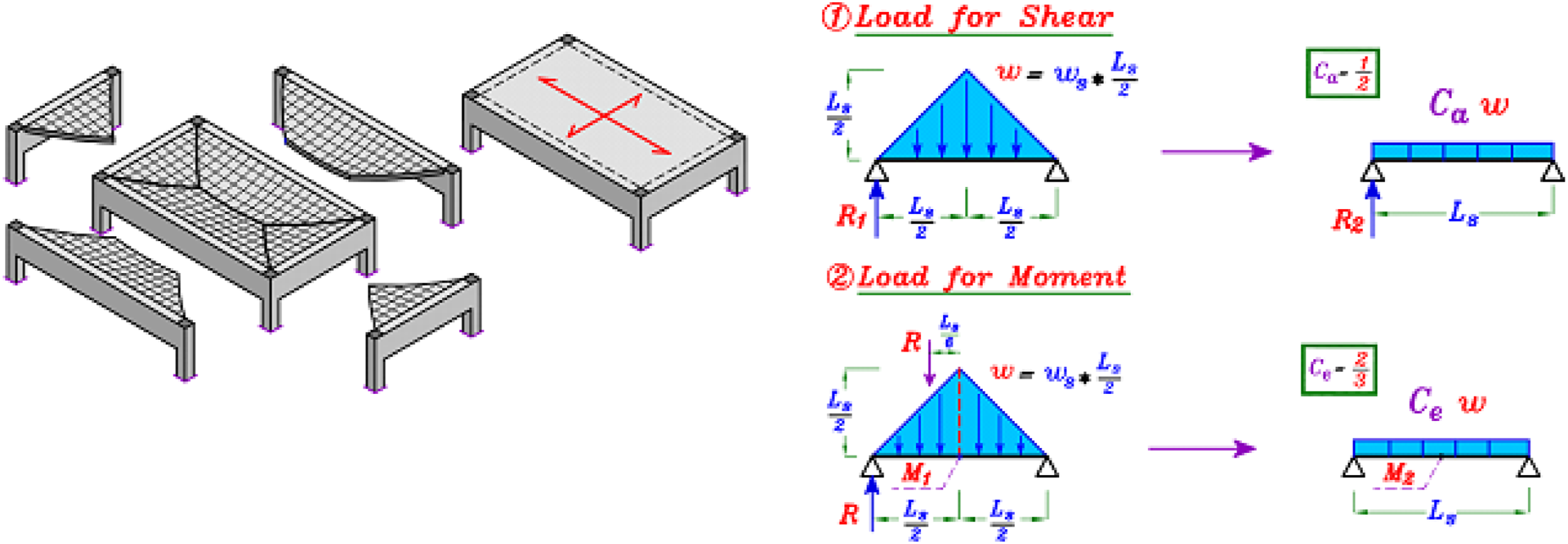
Models with slab
Incorporating slabs in the models helped prevent collapse. Although some displacements observed were relatively large, the plastic rotations of beams remained very small and did not exceed the limits established by UFC (refer to Figure 5). Generally, the maximum displacements were more significant in the lower multi-story models compared to the higher ones, as shown in Figure 6. Figure 7 presents the node displacement history of the removed column in the 15-story model. The displacement histories of the other models are provided in the appendix. The maximum plastic rotation (PR) of beams in radians (x10-3) observed in the structure. The maximum vertical displacement at the top of the removed load-bearing. Node displacement history of the removed column in the 15-story model: (a) EC; (b) EM; (c) EP; (d) IC; (e) IS and (f) IM.


Failure mechanism and structural system behavior
Models without slab
The failure occurred because, after the removal of the column, the compression and tension zones within the beams shifted. Some beams behaved like cantilevers and failed due to insufficient top reinforcement near the adjacent column to the removed one, particularly at the ends of the upper reinforcement. This behavior was similar to the failure observed during the loss of an external middle column (see Figure 8). In contrast, some continuous beams failed because of inadequate reinforcement at the bottom, as seen with the loss of an interior column, such as in the case of losing the internal corner column in the 3-, 5-, and 9-story models (see Figure 9) (Note that the corner bay was removed for better visualization). Example of initial failure of the top reinforcement (location 1). Example of initial failure of the bottom reinforcement (location 2).

The initial failure location of the studied models.

The areas that collapsed were usually the bays directly connected to the removed column, as well as adjacent bays if continuity extended to one bay in the absence of shear walls. For example, in the external corner case, the collapse was limited to the directly connected area, while in the external middle case, it affected the entire line of external bays. This pattern is particularly relevant for low-rise models. However, in high-rise models, while similar behavior may occur, the collapse can be more severe due to the sudden load from falling elements. Based on the results summarized in Table 4. Most failures were observed at the ends of the top reinforcement in beams near the adjacent column (refer to Figure 8). Extending the length of the top reinforcement bars beyond 1.1 m resulted in a shift of the failure location toward the face of the adjacent columns, as demonstrated in Figure 10. Figures 11 and 12 illustrate the progression of collapse in selected cases. The effect of increasing the length of the top reinforcement bar. The progression of collapse in the 3-story cases. The progression of collapse in the 15-story cases.


Models with slab
The models that included slabs demonstrated effective resistance to progressive collapse following the removal of a vertical element at various locations across different stories. This increased resistance is due to the membrane action of the slabs, which reduced displacements above the removed element, established an alternative load-carrying path, and prevented collapse. Figure 13 shows the redistribution of loads after the removal of a column. As illustrated, most of the load is transferred along the nearest paths, while in some cases, structural elements positioned diagonally to the removed column experienced a reduction in the load they were originally carrying. The redistribution of load following the removal of the column: (a) EC; (b) EP; (c) EM; (d) IC; (e) IS; (f) IM.
Compared to the models without slabs, where structural elements were unable to redistribute the loads effectively, the results highlight that ignoring the contribution of slabs and considering only beams is insufficient for preventing collapse. Therefore, analyzing progressive collapse without considering the presence of slabs may lead to misleading conclusions. This highlights the importance of including slabs as essential structural elements in solid slab systems.
Furthermore, when the structure is accidentally subjected to loads significantly higher than the design load (assuming 2 times greater), the presence of slabs helps to limit the spread of collapse. They provide additional confinement, preventing the failure from extending beyond the bays connected to the removed element. This behavior is illustrated in Figure 14, which shows the response of the 3-story model under the external column removal scenario. The progression of collapse in the External Middle 3-story model with slab.
A more detailed investigation into failure mechanisms revealed distinct behaviors across different building heights and slab configurations. In models without slabs, the absence of diaphragm action significantly reduced load redistribution capacity, resulting in early hinging and shear failure at the beam-column joints, especially following corner and edge column removal. In contrast, models with slabs exhibited improved redundancy due to enhanced load-sharing mechanisms through the slabs, which acted as secondary load paths. For shorter buildings (3–5 stories), the collapse typically initiated at the ends of top beam reinforcements adjacent to the removed column, indicating a local flexural failure mode. As building height increased (9–15 stories), global instability and vertical progressive collapse were more prevalent, often triggered by insufficient energy dissipation following dynamic amplification. The presence of slabs delayed these failures by improving continuity and stiffness across floor levels. These observations align with previous findings on load redistribution in slab-beam systems and underscore the importance of considering both local detailing and global geometry when evaluating progressive collapse resistance.
The results reveal that the presence of slabs significantly alters the collapse mechanisms by enhancing load redistribution capacity, especially in higher-story buildings. For example, in the 3-story models without slabs, failure occurred almost immediately following column removal due to insufficient alternate load paths. In contrast, the same scenario in the 9- and 15-story slab-included models resulted in localized damage and redistribution of loads, preventing total collapse. Additionally, variations in initial failure locations were observed based on changes in reinforcement anchorage and slab interaction. The parametric results are now organized to highlight how progressive collapse potential changes with each variable. These findings confirm that slab contribution becomes increasingly critical as the building height increases, due to the growing demand on continuity and diaphragm action for structural integrity. By isolating and comparing these effects, the expanded results clarify the complex interplay between structural height, slab presence, and reinforcement detailing in progressive collapse scenarios, thereby providing deeper insights into the failure mechanisms and system-level response.
Sensitivity analysis of key parameters
To further strengthen the robustness of this study, a sensitivity analysis was conducted to assess the influence of key structural parameters on progressive collapse behavior. Specifically, the analysis focused on buildings of different heights, 3, 5, 9, 12, and 15 stories, while maintaining a constant slab thickness of 150 mm in all models. The beam reinforcement detailing was designed in accordance with the Turkish Building Earthquake Code (TBEC-2018) to ensure realistic and code-compliant conditions. Although the slab thickness was kept uniform, the different building heights provided insight into how vertical redundancy and dynamic amplification effects impact collapse resistance. The results revealed that as the number of stories increased, the structures generally demonstrated reduced residual displacements due to enhanced global stability but also exhibited greater susceptibility to dynamic amplification effects. The findings underscore the critical role of building height and realistic beam reinforcement detail in determining the progressive collapse performance of RC buildings, reinforcing the importance of accurate modeling in collapse assessments.
Conclusions
A Nonlinear Dynamic Procedure (NDP) using the Alternate Path Method (APM) was conducted to assess the resistance of buildings designed according to the Turkish Building Earthquake Code - 2018, in line with United Facilities Criteria (UFC) guidelines. The buildings varied in height, with stories selected as 3, 5, 9, 12, and 15. Both configurations with and without slabs were analyzed. Following UFC recommendations, different locations within the building plan and at various story levels were evaluated for element removal. Based on the analysis of over 240 cases, the following conclusions can be made; however, further studies on different structural configurations and load conditions are suggested for broader insights. • Slab Contribution Prevents Collapse: ◦ Models incorporating slabs consistently satisfied UFC criteria. ◦ Beam plastic rotations remained ≤0.008 rad. ◦ Peak displacements at column removal points are constrained to 20–100 mm. • Failure Mechanisms in Slabless Systems: ◦ All slabless models experienced progressive collapse initiated by bending-induced reinforcement rupture. ◦ 85% of failures originated at top reinforcement terminations. ◦ Extending top bars ≥1.1 m (18% span length) shifted failure locations to the column. ◦ Shear walls limited collapse propagation to 1–2 bays. • Robust Collapse Containment with Slabs: ◦ Slab-inclusive models demonstrated superior performance. ◦ Zero collapse occurrences across 120+ removal scenarios ◦ Localized damage, if any, confined to ≤1 bay • Height-Dependent Performance ◦ In comparisons between 3-story models and 15-story models, structures exhibited 20%–30% up to 50% in some cases, larger displacements (except IM scenarios).