
Abstract
Keywords
Introduction
As the backbone of urban rail transit, subway transportation has the advantages of safety, speed, large volume, convenience, energy saving, less pollution than road and air transportation, and is not restricted by natural climate conditions. 1 In recent years, people’s demand for quality of life is getting higher and higher, and the vibration and noise caused by the vibration of urban rail transit have aroused more and more strong reactions from the public.2,3 At present, in countries with more developed urban rail transit, the research on vibration caused by subway has become an important topic, and the vibration hazard caused by subway has been listed as one of the seven major environmental hazards in the world. Therefore, it is urgent to control vibration caused by urban rail transit.4,5
The control of environmental vibration and secondary structure noise can be divided into three aspects:6,7 source control, propagation path control, and receiving source control. At present, it is generally believed that reducing the incentive of interaction between wheel and rail is a source control measure. 8 Reducing the transmission rate of wheel-rail force to the vibrating object is considered as propagation path control. The implementation of measures near the vibrating object is called receiving source control. (1) In terms of the improvement of source control, wheel/rail grinding 9 is an effective measure to reduce vibration because the surface of the new wheel/rail itself is not smooth, after a period of operation, due to braking, wheel idling, and other phenomena, it will also make the wheel uneven and wheel flat, which will increase the wheel-rail interaction and vibration. (2) The vibration attenuation fasteners are widely used measure in improving the control of the propagation path. Commonly used vibration attenuation fasteners are double nonlinear fasteners (GJ-III), Colon egg fasteners, floating rail fasteners (Vanguard fasteners), Lord fasteners, etc. 10 The tracks commonly used in subway with high vibration reduction effect mainly include elastic short sleeper, 11 longitudinal sleeper, floating slab track, 12 and embedded track. 13 In terms of improving the soil propagation path, the surrounding rock of the tunnel has a good vibration reduction effect, so the vibration reduction measures of the tunnel and roadbed are mostly realized through the surrounding transfer media. In addition, empty ditch, filled ditch, and continuous pile wall system all belong to the category of vibration isolation barrier, which can reduce vibration by making the vibration caused by train operation reflect, project and diffract at the barrier position. 6 (3) In the improvement of receiving source control, the main measures taken for buildings, equipment, and other structures are to set up vibration reduction structural devices. 14 In addition, by adding damping elements inside the building and adjusting structural stiffness, the vibration reduction of the building itself can be achieved to a certain extent.
At present, there are many researches on the vibration attenuation effect of a single type of fastener/track measure, but there are few researches on the stiffness matching of two types of measures. In a certain subway line in China, the existing railway adopts the longitudinal sleeper track matching DT-III ordinary fastener, and it is expected that the longitudinal sleeper track matching Vanguard vibration attention fastening (see Figure 1) can further reduce the comprehensive tunnel vibration by 5 dB(Z). However, the measured results show that the Z-weighted vibration level of the tunnel wall is 77.4 dB(Z) before the reconstruction and 76.4 dB(Z) after the reconstruction, which is only reduced by 1 dB(Z). The matching of longitudinal sleeper track and Vanguard fastener both with attention effect does not achieve the expected greater vibration attention effect. Photo of longitudinal sleeper track reconstruction site.
In the research methods of environmental vibration prediction, the research methods mainly include field measurement method, analog test method, standard empirical formula method and numerical simulation method. (1) Field measurement method. Field measurement method is the most direct and effective evaluation method, through the test instrument to obtain the vibration of the vibration source, the surface and sensitive buildings, can most truly understand the impact of environmental vibration degree and law. However, this method is only effective for existing lines and buildings, and is not suitable for projects under construction or not under construction. (2) Analog test method. When the physical parameters of the research object and the analog object are similar (line condition, vehicle standard, structure type, soil condition and track structure type, etc.), the vibration of the analog object can be used for the research object. The method is simple and easy to implement, and the research period is short. However, the similar conditions of physical parameters need to be strictly controlled. (3) The commonly used prediction correction formula mainly refers to the relevant standards, and can make appropriate corrections to the vehicle, speed, line condition, track state, and structure type. It is the most common method to predict the environmental vibration of sensitive points quickly and accurately by combining the measured or analog vibration. However, it is more dependent on the accuracy of the vibration of the source strength. If the source strength cannot be obtained accurately, it cannot be accurately predicted. (4) With the rapid development of finite element and other modeling technologies, numerical simulation method is the most commonly used research method to predict subway environmental vibration. This method can fully show the dynamic influence parameters of the calculation area, deeply reveal the process of vibration generation and propagation, and obtain the influence of various factors and conditions. It is suitable for the analysis in the early stage of project construction, but it is necessary to verify the model to make effective prediction.
Based on the above research basis, the reasons for the poor matching effect between longitudinal sleeper track and vanguard fastening remain to be analyzed. This paper intends to use the infinite long period track model and Fourier counting method to establish the wheel-rail interaction model, take the wheel-rail interaction force as the excitation of 2.5D FE-BE model,15,16 establish the longitudinal sleeper environmental vibration prediction model, and carry out the field test research on a railway line. The validity of the numerical model is determined by comparing the field experiment with the numerical simulation. On the basis of the above, the stiffness matching strategy of longitudinal sleeper and fastener to reduce tunnel wall vibration is explored by using the verified numerical model.
Numerical model
The environmental vibration caused by trains involves a series of complex mechanical systems, including vehicle-track interaction model and tunnel-ground environmental vibration prediction model. Because the tunnel-ground system has a very large mass and stiffness, the impact on wheel-rail interaction is relatively small, so the calculation of environmental vibration can be divided into the following steps: (1) Considering the vehicle-track structure as an independent interaction system (i.e., assuming that the track structure is supported on a rigid foundation). Fourier series method is used to calculate the force transferred from the track to the tunnel (section 2.1); (2) Considering the infinite longitudinal length of the tunnel and the ground, the semi-infinite characteristics of the ground and the stratification of the soil layer, the tunnel-ground environmental vibration prediction model is established based on the 2.5D FE-BE method, and the bottom force of the track obtained from step (1) is used as the input of the tunnel-ground model (section 2.2); (3) The vibration of tunnel wall of a subway was predicted according to the above method, and the validity of the prediction model was verified by comparison with the experimental results (section 3); (4) Stiffness matching strategies were analyzed by using the tunnel wall acceleration values calculated in step (2) and the stiffness settings of different layers of the track (section 4).
Vehicle–track interaction model
Vehicle model
In the model of vehicle–track interaction, the theory of infinite period structure is applied to consider the periodic and infinite length characteristics of track structure, and the interaction force between wheel and rail is calculated by Fourier series method. The method is divided into three parts: 2.1.1 multi-rigid vehicle model; 2.1.2 ballastless track model of infinite long period structure; 2.1.3 wheel-rail interaction.
The vehicle model is simulated according to the structure of the actual operating vehicle. A multi-rigid body vehicle model is adopted, as shown in Figure 2, which consists of a car body, 2 bogie frames and 4 wheelsets, which are connected by spring-damping units. Multi-rigid body vehicle model.
The differential equation of vehicle vibration8,17 is shown in equation (1).
Track model of infinite long period structure
The vibration model of longitudinal sleeper track is established by using the theory of infinite long period structure.
18
The rail is simulated by Timoshenko beam and the track plate is calculated by mode superposition method. As shown in Figure 3. Track model of infinite long period structure.
The 2.5-dimensional equation of longitudinal sleeper rail
18
vibration is as follows.
Wheel–rail interaction model
The wheel–rail interaction model
19
is shown in Figure 4. Wheel–rail interaction model.
The displacement relationship19,20 between wheel and rail can be obtained as follows. In this paper, the wheel–rail force is calculated in frequency domain.
2.5D FEM-BEM environmental vibration prediction model
This section considers the longitudinal infinite length of the tunnel and the ground, the semi-infinite characteristics of the ground, the stratification of the soil layer, the structural characteristics of the tunnel, etc., according to which a 2.5D FEM-BEM13,14 tunnel-soil model is established, as shown in Figure 5. 2.5D FEM-BEM tunnel-soil model.
Assuming that element A in the 2.5D finite element has 
Assuming an excitation force vector 
Based on this, the motion differential equation for the element is:
It can be expressed as:
Following the general equation of the boundary element method, we establish the boundary integral equation by selecting points on the boundary Γ in equation (7). By discretizing equation (7) for a boundary with N nodes, we obtain the following boundary element equation:
In this equation, the displacement and driving force at node i can be represented as 

Field test and model validation
The frequency response function (FRF) test, the rail roughness test of the corresponding section and the tunnel wall vibration test of the dynamic passage of the train were carried out on the track with the longitudinal sleeper matching DT-III type fastener. The stiffness parameters of the fastener can be derived through the FRF test, which can be used to input the parameters of the fastener of the simulation, and the rail roughness test results can be used as the rail roughness input of the simulation. Finally, the environmental vibration prediction model established in Section 2 is used to predict the tunnel wall vibration to verify the effectiveness of the model.
FRF test
The FRF is test on the track with the longitudinal sleeper matching DT-III type fastener. FRF test photo of longitudinal sleeper track is shown in Figure 6. FRF test results are shown in Figure 7. It can be seen from Figure 6 that the frequency corresponding to the first peak is 264 Hz, and the stiffness can be calculated to be 104 MN/m. According to the half-power bandwidth method, the damping can be deduced to be 0.124, and the spacing of fasteners can be measured by a ruler to be 0.63 m. In this way, the fastener parameters needed to establish the track model can be obtained from the FRF test results. FRF test photo of longitudinal sleeper track. FRF test results of longitudinal sleeper track.

Rail roughness test
The Corrugation Analysis Trolley (CAT) is used to measure the roughness of the rail. CAT is installed on the rail to measure the rail roughness on the rail surface. Its biggest advantage is that it can measure the long-distance rail roughness condition in a short period of time, which is very suitable for measuring and analyzing the rail roughness in one section. Figure 8 shows the photo of rail roughness test. Figure 9 shows the test result of rail roughness. It can be seen from Figure 9 that the rail surface condition is very good, and there is no rail corrugation or severe rail roughness. Photo of rail roughness test. Test result of rail roughness.

Tunnel wall vibration test of the dynamic passage of the train
Reference to standard GB/T 19846-2005 “Mechanical Vibration—Measurement of vibration in Railway tunnels caused by train passage,” the tunnel wall measurement point is set on the longitudinal sleeper track test section. The tunnel wall vibration test layout diagram and sensor layout photo are shown in Figure 10. The sensor sensitivity is 500 mV/g. Its measuring range is 10 g, and the sensor’s frequency is applicable from 0.35 Hz to 5000 Hz. Tunnel wall vibration test layout diagram and sensor layout photo.
Model verification
Longitudinal sleeper track structure parameters.


The predicted and the test result of tunnel wall accelerations.
It can be seen from Figure 11 that both test and prediction results show a trend of first increasing and then decreasing, and both show a maximum value near 40 Hz (wheel-rail P2 resonance frequency). The overall trend of test is basically consistent with that of prediction, and the error is small. The Z-weighted vibration level of the tunnel wall is 81.4 dB(Z) and 81.6 dB(Z), respectively, and the error is small, indicating that the prediction model can well reflect the vibration of the vehicle running through the tunnel wall observation point. The difference of low frequency vibration results is mainly related to the input difference and randomness of long wave irregularity. 21
Predicted results
Based on the verified simulation model, this section will analyze the comprehensive matching of fastener stiffness and track vibration isolation frequency. And then the influence of the single parameter change of the longitudinal sleeper isolation frequency and the fastener stiffness will be analyzed.
Matching strategy study of trapezoidal track sleeper and fastening system
This section studies the matching relationship between fastener stiffness and longitudinal sleeper isolation frequency based on the established model. Among them, longitudinal sleeper track isolation frequency selection includes 5 parameters: 20 Hz, 30 Hz, 40 Hz, 50 Hz, and no isolation effect 5 groups. The fastener parameters were selected as 104 kN/mm (loss factor 0.12), 78 kN/mm (loss factor 0.12), 57 kN/mm (loss factor 0.12), 35 kN/mm (loss factor 0.12), and 12 kN/mm (loss factor 0.12) in 5 groups. The effect of fastener stiffness and track isolation frequency matching on the Z-weighted vibration level of tunnel wall is studied under the condition of small fastener loss factor. Figure 12 shows the Z-weighted vibration level of tunnel wall cloud map corresponding to the matching of the fastener stiffness and the longitudinal sleeper track isolation frequency when the loss factor of the fastener is 0.12. Z-weighted vibration level of tunnel wall cloud map corresponding to the matching of the fastener stiffness and the longitudinal sleeper track isolation frequency (loss factor of the fastener: 0.12).
As can be seen from Figure 12: (1) In the parameter matching between fastener stiffness and longitudinal sleeper track isolation frequency, there are local maximum and minimum values, the maximum value appears at the 35 kN/mm of fastener and 50 Hz of track isolation frequency, and the minimum value appears at the 100 kN/mm of fastener and 20 Hz of track isolation frequency. (2) When the vibration isolation frequency of the longitudinal sleeper track is near 50 Hz, the vibration reduction effect is not obvious when the stiffness of the fastener is selected in the range of 20∼90 kN/mm, and even when the small stiffness of the fastener is matched, there are vibration amplification phenomena in some locations. When the isolation frequency of the longitudinal sleeper track is 30–50 Hz, changing the stiffness of the fastener has little impact on vibration reduction. When the isolation frequency of the longitudinal sleeper track is less than 30 Hz, the stiffness of the fastener is not the smaller the better. The stiffness of the fastener with larger stiffness has a better combined vibration reduction effect than that of the small stiffness fastener. And this is also the reasons for the poor vibration reduction effect of the existing longitudinal sleeper matching floating rail fastener (low stiffness).
Figure 13 shows the Z-weighted vibration level of tunnel wall cloud map corresponding to the matching of the fastener stiffness and the longitudinal sleeper track isolation frequency when the loss factor of the fastener is 0.3. Z-weighted vibration level of tunnel wall cloud map corresponding to the matching of the fastener stiffness and the longitudinal sleeper track isolation frequency (loss factor of the fastener: 0.3).
By comparing Figures 12 and 13, it can be seen that the overall distribution law of tunnel wall vibration is close when the fastener loss factor is increased, but no vibration amplification occurs when the fastener stiffness matches the isolation frequency of the longitudinal sleeper track, and the local minimum value appears at the fastener stiffness of 60 kN/mm and the vibration isolation frequency of 20 Hz, indicating that the loss factor changes will have some influence on the optimal position of matching the fastener stiffness with the isolation frequency of the longitudinal sleeper track.
Effect of longitudinal sleeper isolation frequencies on tunnel wall vibration
Based on the study of Section 4.1, Figure 14 shows the frequency and total value of Z-weighted vibration level of tunnel wall corresponding to different longitudinal sleeper isolation frequencies when the fastener stiffness is 55 kN/mm at the speed of 70 km/h. The fastener loss factor is 0.12. The longitudinal sleeper isolation frequency is defined as Effect of longitudinal sleeper isolation frequencies on Z-weighted vibration level of tunnel wall: (a) Spectrum; (b) total value.
Effect of fastener stiffness on tunnel wall vibration
Based on the study of Section 4.1, Figure 15 shows the frequency and total value of Z-weighted vibration level of tunnel wall corresponding to different fastener stiffness when the longitudinal sleeper isolation frequency is 35 Hz (fastener stiffness is sensitive to this selected vibration isolation frequency) at the speed of 70 km/h. It can be seen from Figure 15 that the vibration of tunnel wall does not gradually decrease as the stiffness of fasteners decreases, indicating that when the track vibration isolation frequency is relatively small, matching fasteners with smaller stiffness is not the optimal choice. That is, the combination of vibration isolation track and vibration isolation fastener does not necessarily have a better vibration reduction effect. In this way, the conclusion of 4.1 is again verified quantitatively. Effect of fastener stiffness on Z-weighted vibration level of tunnel wall: (a) Spectrum; (b) total value.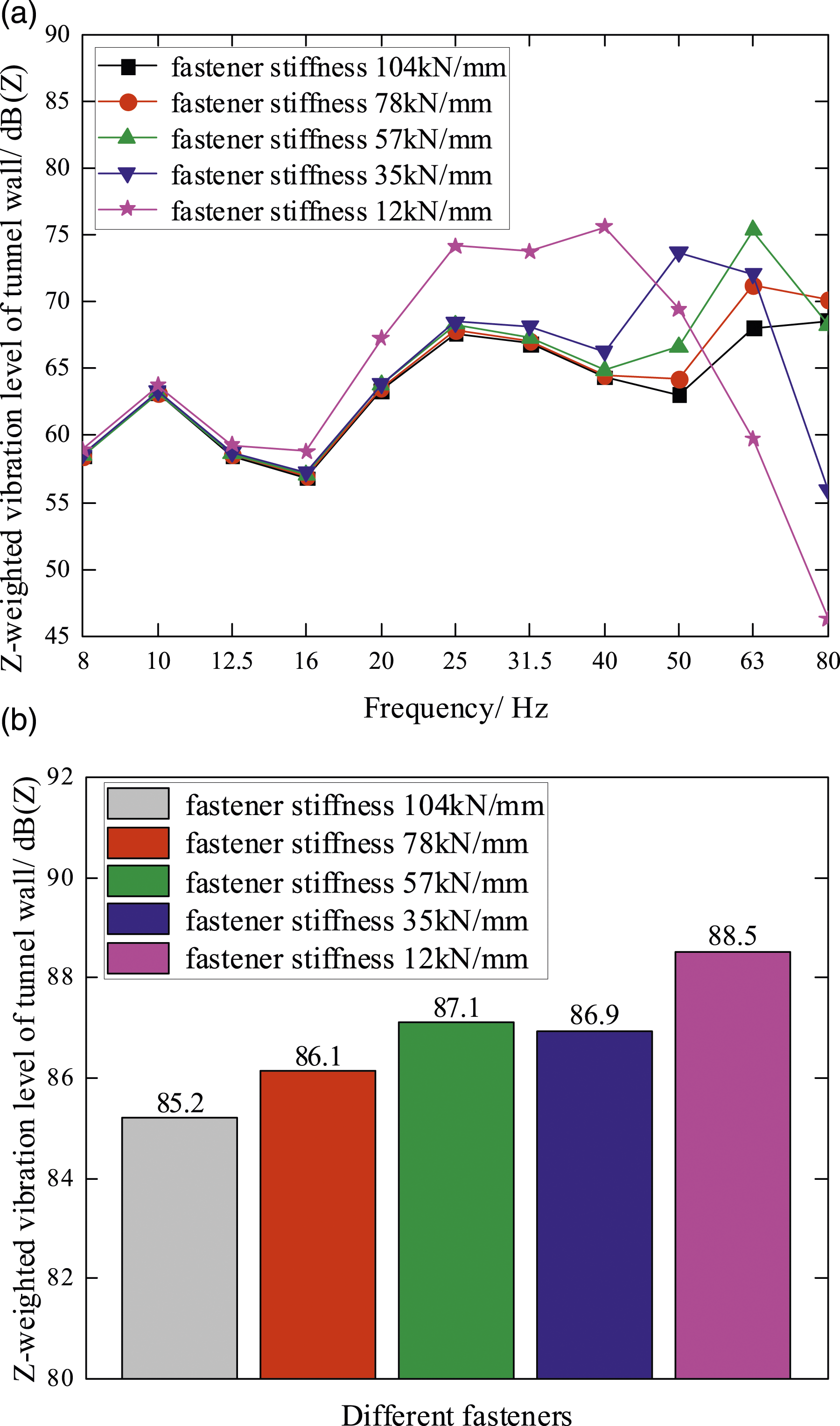
Conclusions
The environmental vibration prediction model of longitudinal sleeper track is established by using the theory of infinite long period structure and the 2.5-dimensional finite element and boundary element (2.5D FE-BE) environmental vibration prediction model. The validity of the numerical model is determined by comparing the field experiment with the numerical simulation. The matching strategy of the supporting stiffness for vibration reduction of longitudinal sleeper and fastener are summarized. (1) When the isolation frequency of the longitudinal sleeper track is less than 30 Hz, the stiffness of the fastener is not the smaller the better. The stiffness of the fastener with larger stiffness has a better combined vibration reduction effect than that of the small stiffness fastener. And this is also the reasons for the poor vibration reduction effect of the existing longitudinal sleeper matching floating rail fastener (low stiffness). (2) The loss factor changes will have some influence on the optimal position of matching the fastener stiffness with the isolation frequency of the longitudinal sleeper track. The matching of the supporting stiffness for vibration reduction of longitudinal sleeper and fastener need to consider the loss factor of fastener.
It is suggested that the matching of track vibration isolation frequency and fastener stiffness/damping should be considered instead of single factor in the design of track vibration reduction. For conventional loss factors (0.1∼0.3), it is recommended to refer to Conclusion (1). For specially designed high-damping loss factors, the matching diagram should be drawn again in accordance with Section 4.1.