
Abstract
Keywords
Introduction
While conventional media access control (MAC) protocols for wireless sensor networks (WSN) have adopted duty cycling to reduce idle listening, duty cycling leads to energy-latency tradeoff, which is one of the major challenges in designing energy efficient yet low latency WSN MAC protocols. To mitigate the impact of sleep delay on packet latency, recent WSN MAC protocols exploit dynamic duty cycling1–3 or wakeup scheduling.4–9 However, these protocol optimization techniques cannot completely eliminate the idle listening of a radio frequency (RF) communication module since they still require periodic wakeups to check the presence of communication.
A few studies10,11 have investigated the design of a radio wave sensor, which is a small RF circuit, separated from the underlying RF module, to detect only the presence of RF signal. By separating channel monitoring from packet communications, a node with a radio wave sensor can eliminate the periodic wakeup of its RF module. Radio wave sensors can be implemented with only a subset of components from the RF module. However, since the existing designs10,11 exclude any form of amplifiers, it is difficult to detect signals weaker than the minimum signal strength required for passing through a silicon diode. Therefore, the sensing ranges of the existing radio wave sensor designs are much shorter than that of the underlying RF module. This range discrepancy makes it difficult to use the existing designs in practical sensor nodes.
Our previous work 12 introduced a new design of radio wave sensor called RF wakeup sensor that can achieve the same sensitivity as the RF module. Since the RF wakeup sensor does not have to extract any information from a received signal, the amplifier in the RF wakeup sensor is irrelevant to phase distortion. Thus, we can use a simple amplifier, eliminating complex circuits for providing high linearity from the conventional amplifiers. Consequently, the RF wakeup sensor can be implemented using an ultralow power amplifier with minimal circuit elements.
If the RF wakeup sensor has no frequency filtering technique, the number of false-positive wakeups due to unrelated signal will be increased. For this purpose, we use a frequency filter that requires neither mixer nor oscillator to selectively sense signals on the predefined frequency band. Since the frequency used for a communication is higher than intermediate frequency (IF), RF wakeup sensor requires a precise frequency filter with high quality factor (Q factor).
Since the existing WSN MAC protocols1–9,13–25 proposed so far assume sensor nodes with only a general RF communication module, there have been no studies for a MAC protocol that can efficiently utilize the RF wakeup sensor. Therefore, our previous work 12 investigates the design space for a MAC protocol that can maximize the benefit from the around-the-clock carrier sensing of the RF wakeup sensor and proposes an on-demand MAC protocol called ZeroMAC that is the first MAC protocol using radio wave sensor.
However, our previous work 12 was preliminary in terms of both RF wakeup sensor design and the evaluation of ZeroMAC. The design parameters of the RF wakeup sensor such as resistance, capacitance, and inductance were intuitively selected and require verification and optimization. Although our previous evaluation covers the impact of major operations of a sensor node on the network and energy performance, we only presented the total latency and energy figures assuming simplified network settings.
In this article, we first optimize the design of RF wakeup sensor. Through a detailed tuning based on the actual circuit design library, we adjust the circuit parameters of RF wakeup sensor, reducing 4.4% of its energy consumption. In addition, we apply duty cycling to the RF wakeup sensor and improve the energy efficiency of the sensor by more than an order of magnitude with no additional delay.
Second, we present the detailed evaluation of ZeroMAC assuming various network conditions by varying the number of sensor nodes, the number of sources and sinks, the hop distance between a source to a destination, and traffic volume. In addition, we analyze the factors contributing to the energy and the latency, discussing the impact of idle listening, buffering, and control packet overhead on the energy and network performance.
Third, we mathematically analyze the energy and the latency performance of ZeroMAC compared to an ideal MAC protocol and two general models of the conventional WSN MAC protocols. The analysis will present the lower and upper bounds of ZeroMAC’s performance in terms of the power, performance, and cost model of RF wakeup sensor commercially achievable.
For experimental evaluation, we have implemented ZeroMAC on NS-2 simulation platform 26 and compare its energy and latency performance against two representative WSN MAC protocols: X-MAC 25 and A-MAC. 2 By eliminating duty cycling with ultralow power RF wakeup sensor, ZeroMAC completely eliminates the idle listening caused by the periodic wakeups of a RF communication module, reducing the per-node energy consumption by 94.4% and 95.3% in comparison with X-MAC and A-MAC, respectively. In addition, the on-demand wakeup functionality of ZeroMAC allows sensor nodes to communicate with each other without sleep delay since a sender can wake up its receiver by transmitting a short wakeup signal. The simulation results show that 87% of the total transmissions of ZeroMAC suffer neither sleep delay nor buffering delay. As a result, ZeroMAC can deliver data packets at least 1.87 times faster with only 3% of energy consumption compared to both X-MAC and A-MAC, achieving both zero sleep delay and zero idle listening communication for WSNs.
The remainder of this article is organized as follows. Section “Related works” discusses the related works. Section “RF wakeup sensor” presents the detailed design of RF wakeup sensor and analyzes its circuital characteristics and energy efficiency. Section “ZeroMAC: zero idle listening and zero sleep delay MAC protocol” investigates the design space of a WSN MAC protocol that can be built with the RF wakeup sensor and introduces ZeroMAC protocol. The section also analytically and experimentally evaluates the energy and the latency performance of ZeroMAC compared to X-MAC and A-MAC. Finally, section “Conclusion” concludes the article.
Related works
There have been a few studies10,11 for a radio wave sensor. However, it is hard to apply the existing radio wave sensors to wireless sensor nodes since the sensors designed so far have shortcomings: additional wakeup channel and insufficient sensitivity. Passive RF Wake-up (PRFW) 10 is one of the pioneering studies that assume an additional wakeup channel. PRFW adds ATA5283 and ATA5276 modules, which use 125 kHz frequency band, to sensor nodes. ATA5283 is a signal detector and ATA5276 is a signal generator. However, PRFW requires additional frequency band dedicated for wakeup signal, and the sensing range of ATA5283 is only a few meters, which makes PRFW impractical to be used for real wireless sensor nodes.
The high-sensitivity wakeup circuit (HWC) 11 is another radio wave sensor design assuming complementary metal–oxide–semiconductor (CMOS) technology. It consists of a rectifier, a switch, and a circuit protector. A rectifier acts as a signal detector, which consists of multiple diodes. However, a signal has to be stronger than −30 dBm to pass through a (CMOS) diode. Therefore, the maximum sensitivity of HWC is −30 dBm while CC1000, 27 which is a popular communication module for WSNs, provides −99 dBm sensitivity at 38.4 K baud rate. Therefore, it is impractical to apply HWC to WSNs since the difference between the sensitivities of HWC and CC1000 is about 69 dBm. According to the Friis equation, a 69 dBm difference in sensitivity implies a range difference of 3000 times. While CC1000 can transmit a packet over 300 m, the maximum distance of HWC 11 is only 10 cm according to the Friis equation.
RF wakeup sensor
RF wakeup sensor is a dedicated radio wave sensor to detect the presence of communication by sensing a carrier signal. In other words, RF wakeup sensor separates a channel monitoring function from a RF communication module. If a RF wakeup sensor detects a signal that has higher strength than the predefined threshold, the RF wakeup sensor interrupts the processor to notify the communication occurrence. The processor generates a turn-on signal to activate a RF communication module. Figure 1 shows the structure of a sensor node with a RF wakeup sensor. With RF wakeup sensor, a sensor node can turn off its RF communication module.

The structure of a sensor node with a RF wakeup sensor.
Design methodology
To design the RF wakeup sensor, it is necessary to understand the signal processing mechanism of a general RF module. Since carrier signal detection is a part of the signal processing mechanism, RF wakeup sensor can be designed by simplifying a basic RF module. We assume a superheterodyne receiver module such as CC1000 as a baseline RF module. Figure 2 shows the block diagram of CC1000.

Block diagram of CC1000.
A mixer and a voltage-controlled oscillator (VCO) are required to shift the frequency of an incoming signal to the IF. A mixer needs an additional signal from the VCO, which is the most energy-consuming component in a RF module. To design an ultralow power RF wave sensor, we need to eliminate both the mixer and the VCO from our design. Note that both of them are used for frequency shifting. If we can directly process an incoming signal without frequency shifting, these components can be eliminated. Fortunately, our RF wakeup sensor tolerates inter-symbol interference since it does not have to extract information from an incoming signal. Instead, RF wakeup sensor needs to detect only the presence of a signal on the channel. Thus, we can eliminate both components from our design. Instead, we add a frequency filter to select the predefined channel. Since the RF communication frequency is higher than IF, RF wakeup sensor requires a precise frequency filter and inductors with high quality factor (Q factor).
In an IF stage, an amplifier reports received signal strength (RSS), which is estimated by an automatic gain control (AGC). The AGC controls the gain of the amplifier. The output signal of an AGC has a constant power level, which should be strong enough to be processed in the following demodulator. Note that RF wakeup sensor does not require RSS values. It only needs to report true or false information on whether the RSS is higher than the predefined threshold. Therefore, a simple signal detector can replace the energy-consuming AGC.
A demodulator is used in a RF module to recover the information from the incoming modulated signal. We can also eliminate the demodulator from our design since the RF wakeup sensor does not require extracting any information from an input signal. Consequently, RF wakeup sensor consists of a low noise amplifier (LNA), a frequency filter, and a signal detector.
RF wakeup sensor design
Before designing the RF wakeup sensor, we need to investigate the communication range of a RF communication module. In this article, we refer to the specification of CC1000. 27 We use Dongbu HiTek’s 0.13 µm RF CMOS technology. 28
Overview of RF wakeup sensor design
Figure 3 shows the circuit design of RF wakeup sensor, which consists of a multistage amplifier, a bandpass filter, and a detector. This design also includes the interrupt port to a processor since the resistance of the interrupt port should be considered for impedance matching. As shown in this design, RF wakeup sensor has neither a mixer nor a VCO that are heavy consumers of an energy source. In addition, all the other devices except an amplifier are passive devices that do not consume energy. RF wakeup sensor uses a multistage cascade amplifier to reduce the energy consumption.

The circuit design of RF wakeup sensor.
Detector
A detector in RF wakeup sensor has two roles: detecting a communication signal and generating an interrupt signal. If the strength of an incoming signal is higher than the predefined threshold, a detector interrupts the processor. These operations are simply implemented by treating the incoming signal as an input to a switch for interrupt signal generation. Therefore, we use a general low-power rectifier to convert an incoming AC signal into a DC switching signal. The capacitor linked with the transistor gate in a voltage sensor secures power for the transistor and eliminates ripples on the output signal of the detector. Figure 4 shows a signal detector that consists of a rectifier and a voltage sensor.

The circuit design of a signal detector.
The response time of the RF wakeup sensor depends on the design parameters of a detector since the parameters affect the time for charging a capacitor within the detector. To analyze the response time, we first calculate the minimum signal strength that can be sensed by the detector,


where


where


The interrupt pin of a processor is a pull-up switch that uses the output signal of the detector as its triggering signal. The pull-up switch generates an interrupt signal when
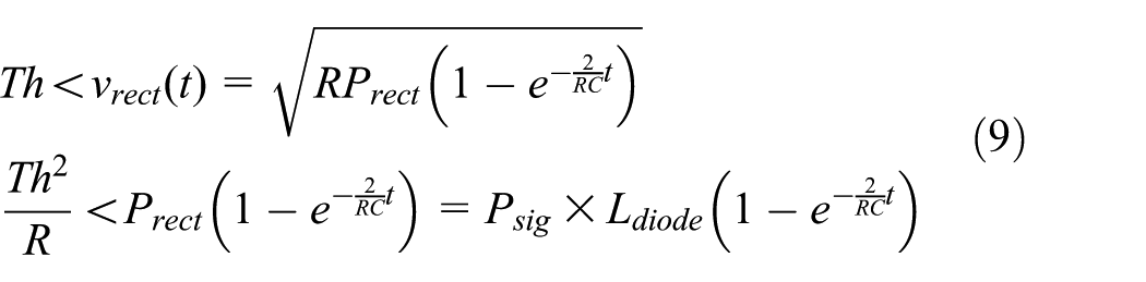

We can decrease


where
To achieve the maximum sensitivity with low ripple signal, we select a 10 pF capacitor and a 900 kΩ resistor. The power loss of diode,
Amplifier
An amplifier in RF wakeup sensor should have at least 69 dB gain to make −99 dBm communication signal pass through the signal detector that can detect only −30 dBm signal. Since an amplifier needs bias current, it consumes energy due to leakage current when there is no RF signal. Therefore, to design a low power RF wakeup sensor, it is important to minimize the energy consumed by the amplifier. However, we need to consider the tradeoff between the energy consumption and the gain of an amplifier. We can use a single 69 dB amplifier with high energy consumption or multiple low gain amplifiers with low energy consumption. We analyze the tradeoff and find the optimal parameters for the elements of an amplifier in the following discussions.
Since an incoming signal can be very small in its strength, an amplifier must be robust to a background noise. A cascode LNA stacks transistors by connecting the source of a transistor with the drain of another transistor. Generally, most of LNAs for microwave system exploit a cascode structure since a cascode LNA has a higher gain and a superior linearity than a cascade LNA when they use the same amount of current. Therefore, we design an amplifier based on a cascode structure. Figure 5 shows our low power cascode amplifier.

The circuit diagram of RF wakeup sensor.
Bias current and RF chock
The energy consumption and the gain of an amplifier depend on bias current. Low bias current reduces both energy consumption and gain. Therefore, we need to find the optimal parameters to maximize gain/power, which depends on transistor size and RF chock. Figure 6 shows that the gain per microwatt increases as the amplifier uses more power. Intuitively, the highest gain/power leads to an optimal parameter. However, we need to consider impedance matching.

Gain per unit power consumption (1 µW).
Impedance matching
In an RF circuit, impedance matching is the practice of designing the input impedance of an electrical load or the output impedance of its corresponding signal source to maximize the power transfer and to minimize reflections from the load. If we fail to match the impedance, a circuit may lose the incoming signal due to reflections. We need to find optimal parameters both to match the impedance and also to make the amplifier to meet the 50 Ω standard for microwave hardware.

If we transpose 1/


Therefore, the reactance value of parallel components is given by

The imaginary part is given by

According to the signs of
Bandpass filter
If the RF wakeup sensor has no frequency filtering, the number of false-positive wakeups due to unrelated signal will be increased. Therefore, we use a frequency filter that requires neither mixer nor oscillator to selectively sense a signal on the predefined frequency band. The Q factor of a frequency filter is inversely proportional to the bandwidth of a passband. Since the frequencies used for communication and for an IF stage are 915 MHz and 150 kHz, respectively, RF wakeup sensor, which operates on 915 MHz, requires a narrow-band filter while a conventional RF communication module requires a wide-band filter for its IF stage. Therefore, the frequency filter within RF wakeup sensor will have a high Q factor that leads to a high inductance for an impedance matching network. Although the proposed filter assumes that they are implemented on the outside of a CMOS chip, the filter can be simply converted into a bulk acoustic wave (BAW) filter that can be implemented on a CMOS chip.
Duty cycling of RF wakeup sensor
We assume that both the RF wakeup sensor and the communication module use the same channel. With a RF wakeup sensor, a wireless sensor node can wake up its neighbors with a short signal, which is strong just enough to charge the capacitor within a signal detector. We call this signal as

The communication process with the wakeup signal.
Although the RF wakeup sensor can reduce the energy by turning off the communication module, it still consumes energy due to the leakage current on the amplifier. To further improve the energy efficiency of the RF wakeup sensor without performance degradation, we apply duty cycling to the RF wakeup sensor. A duty cycle,

Wakeup signal response of RF wakeup sensor with duty cycling.
As we analyze the response time in section “RF wakeup sensor design,” the response time of the RF wakeup sensor is much shorter than the minimum transmission time of CC1000. Therefore, the RF wakeup sensor need not sense the entire wakeup signal. Yet, to avoid the detection failure, the RF wakeup sensor has to wake up at least once to detect the signal during the transmission of a wakeup signal. As shown in Figure 8, this requires the length of the wakeup signal,

where

Evaluation
To analyze the circuital characteristics and the energy efficiency of our RF wakeup sensor design, we model RF wakeup sensor on Advanced Design System (ADS) 2009 29 using Dongbu HiTek’s 0.13 µm RF CMOS technology.
Amplifier
In the previous section, we designed a multistage amplifier. Figure 9 shows the input and output reflection coefficients and forward transmission characteristics of the amplifier. An input port and an output port are matched to 50 Ω. Consequently, the multistage amplifier has 72 dB gain and consumes 228 µW.

The circuital characteristics of a single-stage amplifier.
As we have discussed in section “RF wakeup sensor,” we target a multistage amplifier for providing 70 dB gain by sequentially linking six single-stage amplifiers. Figure 10 shows forward transmission of the multistage amplifier. To optimize the multistage amplifier, we adjust the bias current to implement a 70 dB multistage amplifier that consumes 218 µW.

The circuital characteristics of a multistage amplifier.
RF wakeup sensor
Figure 11 shows how our design generates an interrupt as a function of incoming signal strength. As shown in this figure, the output signal of RF wakeup sensor drops from 3 to 0 V when the strength of input signal is higher than −99 dBm. This figure also shows the interrupt generation scenario on the neighbor channel: 913 and 917 MHz. RF wakeup sensor interrupts the processor when the strength of an incoming signal on the neighbor channels is higher than −50 dBm. Theoretically, −50 dBm incoming signal comes from a node 1 m apart. Therefore, we can ignore the false-positive wakeups due to communications on the neighbor channel.

Interrupt generations according to channels.
Impact of duty cycling
The duty cycling of RF wakeup sensor will improve the energy performance of RF wakeup sensor by reducing the idle listening but it will degrade the network performance by increasing the packet latency with delayed wakeup. To analyze the impact of the duty cycling on the energy and networking performance, we model energy saving rate and throughput loss due to duty cycling. The energy saving rate represents the energy performance improvement achieved by duty cycling and is defined as the ratio of the energy consumption with full wakeup to the energy consumption with duty cycling. The throughput loss represents the networking performance degradation due to duty cycling and is defined as the network throughput with full wakeup to the network throughput with duty cycling.
To find an optimal duty cycle of the RF wakeup sensor, we first look into the energy consumption of a node. The energy consumption of a sender and a receiver,


Using equation (19), we can express the average energy consumption of a sender and a receiver as a function of the duty cycle


where


where
For a comparative analysis, we assume carrier sense multiple access (CSMA) and CC1000 as a MAC protocol and a communication module, respectively. Figure 12 shows

Energy saving rate with duty cycling.
To further reduce the energy consumption, we can decrease the duty cycle of the RF wakeup sensor by increasing the size of a wakeup signal. However, a long wakeup signal encroaches on a channel bandwidth, resulting in the throughput loss. If we decrease the duty cycle of RF wakeup sensor, we can further reduce the energy consumption. But, the low duty cycle of RF wakeup sensor leads to performance degradation such as throughput loss and additional communication latency. Figure 13 shows the

Energy saving rate-throughput product with duty cycling.
Hardware cost
So far we have assumed that we use discrete circuit elements to implement RF wakeup sensor. However, it would be best if we can use the CMOS VLSI technology to implement the RF wakeup sensor considering the size and the cost efficiency of CMOS implementation. Assuming 0.13 µm process technology, the area size of RF wakeup sensor would be 0.8 × 0.4 mm2 based on the area estimation of each component of RF wakeup sensor for the CC1000. Due to its small chip area, a separate chip would waste at least 33% of a silicon wafer since a general fabrication process requires 0.24 mm margin for a cutting process. As a result, it would be practical to embed RF wakeup sensor into a communication module. According to our evaluation, additional chip area for RF wakeup sensor is 7% of the chip area of CC1000 under the same technology compared to the system on a single chip including a processor and a memory such as AMD Geode LX800. RF wakeup sensor requires only 1% of the total chip area. As a result, with only small hardware cost, we can efficiently improve the energy and the latency performance of a sensor node.
ZeroMAC: zero idle listening and zero sleep delay MAC protocol
Design space for a MAC protocol with RF wakeup sensor
In this section, we investigate the design space of a new MAC protocol with RF wakeup sensor. There are two key issues in designing the MAC protocol: wakeup procedure and sleep procedure. The
For the investigation of these issues, we assume that each node has a RF wakeup sensor and a CC1000 module with 19.2 kbps transmission rate. As we describe in section “RF wakeup sensor design,” a RF wakeup sensor uses a 100 pF capacitor for a signal detector. According to our evaluation with ADS, 29 it takes 4.5 µs to charge the capacitor when we input −100 dBm signal. Under the 19.2 kbps transmission rate, a single bit is long enough to charge the capacitor. However, the minimum signal length that can be transmitted by CC1000 is 1 byte. Therefore, the length of the wakeup signal is 1 byte. Since a RF wakeup sensor does not require decoding the wakeup signal, any bit stream can be used for a wakeup signal. Our scheme uses 1 byte signal that has the same bit pattern as B-MAC preamble. 13
Wakeup approaches: entire versus hop-by-hop
To wake up nodes on a communication path, we can adopt one of two strategies to propagate the wakeup signal: entire wakeup and hop-by-hop wakeup. In the
The energy consumption of the entire wakeup approach would depend on the number of the members in MCDS. In an ideal case where nodes can be placed in predetermined positions, the members of MCDS should be located at the vertices of Voronoi cells.
22
This is illustrated in Figure 14. If we assume that the area of a regular hexagon is almost the same as that of a circle, a single hop transmission range will be overlapped by four nodes and the sum of the overlapped area will be twice that of a single hop transmission range, as shown in Figure 14(a) and (b). Therefore, the effective communication coverage of a node can be regarded as half of a regular hexagon. It means that the number of MCDS members,


Ideal position of the members of MCDS: (a) ideally connected dominating set and (b) ideal MCDS shapes honeycomb.
Since the entire wakeup approach makes all the nodes wake up at every communication event, sensor nodes that are not on the communication path waste energy due to unnecessary wakeups. In addition, it is difficult for each node to determine how long it has to wake up since it does not know when a data packet will arrive at the destination. All the non-participants need to wake up until a packet passes through the maximum hop distance in the network.
In the hop-by-hop wakeup approach, we can reduce the energy consumption of non-participants since only the 1-hop neighbors of a node are waken up during each hop communication. Furthermore, overhearing nodes can sleep immediately after checking the address in a received packet. Therefore, this approach can minimize the energy waste due to unnecessary wakeups. However, the imperfect physical characteristics of a RF wakeup sensor and a RF communication module lead to irregular and indented RF sensing and communication ranges. 23 If the RF sensing range is wider than the communication range, some non-participants cannot receive the following packet. Therefore, they cannot sleep immediately. If the RF sensing range is narrower than the communication range, a receiver node may not detect a wakeup signal from a sender. Fortunately, the receiver node can wake up by detecting a packet as a wakeup signal, and it will be able to receive retransmitted packets. Therefore, the range difference would only lead to longer idle listening and retransmissions.
To compare the overhead of different wakeup procedures, we implement two schemes on NS-2 simulator. 26 We assume that the RF sensing range and the communication range vary according to a standard normal distribution. We use the same parameters as S-MAC 17 for the power consumption of a RF module: 30 mW tx power, 15 mW rx and idle power, and 2 µW sleep power. We assume 230 µW for a RF wakeup sensor.
Figure 15(a) shows the average per-node energy consumption for constructing a MCDS in the entire wakeup approach. In this simulation, we fix the area of the network and vary only the node density. As the number of nodes increases, nodes in a MCDS are located closely, and the number of nodes in a MCDS increases. Therefore, the energy consumption increases as the number of nodes increases.

The overhead of wakeup procedures: (a) the average per-node energy consumption of the entire wakeup approach according to the number of nodes, (b) the average per-node energy consumption according to the number of hops, and (c) the average per-node energy consumption for wakeup signal propagation according to the number of nodes.
Figure 15(b) and (c) shows the wakeup signal transmission overhead as a function of the number of total nodes and the hop distance from a source to a destination. These results do not consider the energy consumption due to idle listening after receiving a wakeup signal. As we expect, the average per-node energy consumption of the hop-by-hop wakeup approach is linear to the hop distance while the entire wakeup approach consumes energy constantly. This is caused by the difference in the number of non-participants that overhear wakeup signals in two approaches. The results confirm that the entire wakeup approach overworks. Since packet transmissions are carried out hop-by-hop style, a source does not have to wake up all the nodes. A sender needs to wake up only its neighbors before starting a packet transmission.
When there is burst traffic, the entire wakeup approach can omit wakeup signal transmissions after the first wakeup signal flooding while the hop-by-hop approach requires repetitive wakeup signal transmissions. Note that the wakeup signal is 1 byte long. The energy consumption for transmitting a wakeup signal is negligible in comparison with idle listening overhead of overhearing nodes. In this simulation, a single wakeup signal transmission consumes about 12 µJ and an overhearing node consumes about 4.95 mJ during a single communication. Thus, the energy consumption overhead of the entire wakeup scheme overwhelms the overhead of repetitive wakeups created by the hop-by-hop approach even for burst traffic.
Impact of sleep procedure
To minimize the energy waste due to idle listening, active nodes need to turn off their RF module as soon as possible. If a node can check when a communication ends or whether it is a non-participant, the node can turn off its RF module. Since both a source and a destination can confirm the end of its communication, they can turn off their RF module immediately. Overhearing nodes also can turn off immediately after checking the target address of a received packet.
However, other nodes may not check the conditions as discussed in section “Wakeup approaches: entire versus hop-by-hop.” Therefore, we use a turn-off timer that will expire after a predefined time. Depending on the wakeup procedure, we need to set the turn-off timer differently. In the entire wakeup approach, nodes need to wake up long enough until a packet to pass through the maximum hop distance. In the hop-by-hop approach, each node sets the timer for a single hop communication.
We evaluate the impact of the turn off control on the energy distribution. In this simulation, a source delivers a single data packet over 5 hops. Figure 16 shows the energy distribution as we vary the number of total nodes. Overhearing denotes the energy consumed by non-participants. Packet delivery denotes the energy consumed by the communication. The entire wakeup approach wastes an enormous amount of energy for idle listening since all the nodes need to wake up during five transmissions. In contrast, the hop-by-hop approach substantially reduces idle listening by limiting the propagation of wakeup signal within the neighbors of the communication path. In addition, the entire wakeup approach consumes more energy for delivering a packet since nodes on the communication path keep idle listening before a packet is delivered to the destination.

The impact of turn-off control.
ZeroMAC protocol
Based on the analysis results from section “Design space for a MAC protocol with RF wakeup sensor,” we now propose a new on-demand MAC protocol called ZeroMAC.
Communication process
As we have analyzed, the hop-by-hop approach has more advantages than the entire wakeup approach. First, the hop-by-hop approach eliminates unnecessary wakeup signal flooding, which would lead to huge overhead due to idle listening. Second, it does not have to construct a MCDS. Thus, ZeroMAC is designed based on the hop-by-hop approach.
Figure 17 shows the communication process of ZeroMAC. It is based on 802.11 distributed coordination function (DCF) 30 except the fact that a wakeup signal is transmitted before starting a communication transaction. We still use request-to-send/clear-to-send (RTS/CTS) exchange to avoid hidden terminal problem in ZeroMAC. Both a sender and a receiver need to broadcast a wakeup signal before transmitting their first control packet. If the receiver skips the wakeup signal, the overhearing nodes of a receiver would wake up when the receiver sends CTS. In this case, they need to keep awake until they receive an acknowledgement (ACK) packet, which would increase unnecessary idle listening.

The communication process of ZeroMAC.
After transmitting a wakeup signal, the transmitter has to wait until its neighbors turn on their RF module. We call this waiting time as
Note that ZeroMAC cannot completely avoid collisions as it employs virtual carrier sensing inherited from 802.11 DCF. In ZeroMAC, a wakeup signal may collide with another wakeup signal or with regular communication packets. If a wakeup signal collides with another wakeup signal, the designated receivers can still wake up normally since they only check the presence of a signal. However, the following RTS packets may collide again as in the previous wakeup signal collision. However, with CSMA procedure with RTS/CTS exchange, the senders can address the collision and carry out the communication process using contention windows, random backoff, and RTS/CTS exchanges.
Let us examine another collision scenario where a wakeup signal collides with regular communication packets. Under an ideal situation where a node has a perfectly circular transmission range, ZeroMAC does not suffer from this collision since all the neighbors of a sender and a receiver will not intrude upon any ongoing communication after detecting a wakeup signal. Unfortunately, in the real world, sensor nodes can suffer from this kind of collision due to the time-varying characteristics of transmission range. In this case, both the ongoing and a new communication may interfere. This leads to repetitive random backoff process, which would increase both the energy consumption and the message latency.
Analytical evaluation
For the following analysis, we assume that
Before we analyze the performance of ZeroMAC, we first investigate the lower bounds of the energy consumption and the packet latency that can be achieved by an ideal WSN MAC protocol. We assume that the ideal MAC protocol allows each node to have complete global information including traffic conditions and the topology information of a given network. Therefore, all the nodes exactly know when they have to wake up to carry out their communications without delay and when they have to sleep to avoid idle listening. In addition, we also assume that a sender can transmit a data packet to its receiver without contention resolution. However, we do not assume an error-free channel. Therefore, the ideal MAC protocol still requires an ACK packet to announce a successful reception. As a result, each node uses its time and energy only to deliver its data and ACK packets. Therefore, the energy consumption and the packet latency for a single data packet delivery from a source to a sink can be expressed by

where

The second term of
Since WSN MAC protocols usually operate in a distributed manner, it is quite difficult for a node to have complete global information as in the ideal MAC protocol. Due to the lack of such global information, each node needs to check the communication state of its neighbors before its communication to resolve potential contentions, resulting in additional time and energy consumption. Therefore, the total energy consumption,

where
Energy consumption
We can express the energy consumption for delivering a single data packet as

Unlike

where
For synchronous scheduling, we assume carrier-sense multiple access with collision avoidance such as 802.11 DCF with RTS and CTS packets. Therefore, with synchronous scheduling, each node periodically wakes up to check for potential communications, going through contention windows and exchanging RTS and CTS packets. As a result, the energy consumption for control operations can be expressed as

where
In contrast, ZeroMAC turns on its RF communication module only when there is traffic. The energy consumption for control operations of ZeroMAC can be calculated as

where
Message latency
In the synchronous WSN MAC protocols with duty cycling such as S-MAC
17
and A-MAC,
2
a data packet can traverse a single hop every cycle. A data packet suffers from sleep delay due to the sleep state of a receiver at every hop. To apply duty cycling, the cycle time of a node is generally longer than or equal to the time for a single data packet transaction, which includes the time for transmitting a data packet and its related control packets. Therefore, we can assume that it takes a single cycle for a data packet to be transmitted to the next node. The latency of the first packet among

The second term is the buffering delay due to consecutive transmissions. To avoid the interference with the previous packet, consecutive packets need to maintain 3-hop distance among each other.
With asynchronous scheduling, the average sleep delay for each transmission would be

In contrast, a sender with ZeroMAC can transmit a data packet to its receiver any time whenever a channel is idle. Therefore, ZeroMAC can deliver data packets without sleep delay. As a result, the average packet latency of ZeroMAC can be expressed by

Comparative analysis
Figure 18 shows the total energy consumption and the message latency as we increase the number of packets generated. For this analysis, we assume that a sender transmits data packets to a receiver where a route from the sender to the receiver is 10 hop. We also assume that each data packet is 100 bytes long while the size of a control packet such as RTS, CTS, and ACK packet is 10 bytes. The error rate of the wireless channel is 0.01. We analyze two different versions of ZeroMAC: ZeroMAC_base and ZeroMAC_opt. ZeroMAC_base uses the minimum duty cycle for RF wakeup sensor without performance degradation.

The energy consumption and the packet latency according to the number of packets: (a) total dissipated energy and (b) average message latency.
ZeroMAC_opt uses the optimal duty cycle of RF wakeup sensor based on the
Figure 18(b) shows the message latency as we increase the number of packets. Compared to the ideal MAC protocol, both synchronous and asynchronous MAC protocols suffer from sleep delay, which accounts for the initial gap among the protocols when a single packet is transmitted. Synchronous protocols suffer from longer sleep delay compared to asynchronous protocols. In contrast, ZeroMAC does not suffer from sleep delay. However, it still takes time in resolving contentions and collisions during contention windows and RTS/CTS exchanges. Overall, ZeroMAC can handle burst traffic more quickly and energy-efficiently than the conventional WSN MAC protocols by completely eliminating the sleep delay.
The analysis results show that the message latency of ZeroMAC_base is only 1.875 times higher than that of the ideal MAC protocol while asynchronous scheduling and synchronous scheduling consume 12.9 and 12.5 times longer time in delivering a message compared to the ideal MAC protocol. Since ZeroMAC_base has no performance degradation due to the duty cycling of RF wakeup sensor, the message latency of ZeroMAC_base shows the lower bound of the latency performance of ZeroMAC. Compared to ZeroMAC_base and the ideal MAC, ZeroMAC_opt marks 5.3% and 97.5% longer message latency, respectively. Since ZeroMAC_opt uses the optimal duty cycle based on the
Figure 19 shows the total dissipated energy and the average packet latency as we vary the duty cycle of a node. For this analysis, we assume a source transmits five packets to a 10-hop distance receiver. Note that the duty cycles in asynchronous and synchronous scheduling determine the sleep period of a communication module while ZeroMAC’s duty cycle determines the sleep period of RF wakeup sensor.

The energy consumption and the packet latency according to duty cycle: (a) total dissipated energy and (b) average message latency.
As shown in Figure 19(a), the total dissipated energy of synchronous scheduling and ZeroMAC are saturated while that of asynchronous scheduling rebounds slightly as we lower the duty cycle. This is due to the fact that the energy consumption for preamble transmission and overhearing increases as we decrease the duty cycle. As discussed in section “Amplifier,” RF wakeup sensor consumes 218 µW to sense a channel while the sleep state of a communication module consumes only 2 µW. In other words, with 100 times lower duty cycle, a conventional RF communication module would consume comparable energy with RF wakeup sensor. According to our analysis, synchronous scheduling with 0.001 duty cycle consumes 31.2% less energy than ZeroMAC with 0.1 duty cycle. However, synchronous scheduling would suffer from excessive sleep delay as we decrease duty cycle.
Figure 19(b) shows the average packet latency of each scheme as we decrease the duty cycle. Note that the minimum cycle time should not be smaller than the time for a single data transaction. Therefore, asynchronous scheduling with 0.01 duty cycle and synchronous scheduling with 0.1 duty cycle mark the lower bound of packet latency of each scheme. Since the response time of RF wakeup sensor is very small, 17.2 µs, compared to the minimum cycle time, 372 ms, the impact of the duty cycling of RF wakeup sensor on the packet latency is negligible. Therefore, the average packet latency of ZeroMAC increases slightly as we decrease the duty cycle of RF wakeup sensor. However, the conventional MAC protocols suffer from excessive sleep delay due to low duty cycle operations as we decrease the duty cycle.
Simulations
We have modeled ZeroMAC using NS-2 simulator. 26 We use X-MAC 25 and A-MAC 2 as reference protocols. We compare both the packet delivery latency and the energy consumption of these three protocols. We assume 400 grid nodes with a central sink node. A source generates 100 packets that are 50 bytes long. We vary the traffic load by changing the packet generation interval on the source node.
Packet delivery latency
Figure 20 shows the average packet latency over 10 hops as we vary the packet generation interval. As shown in the figure, ZeroMAC outperforms both X-MAC and A-MAC for all scenarios. ZeroMAC does not suffer from the sleep delay since a sender can wake up a receiver on demand. All the three protocols suffer from buffering delay when the packet generation interval is small. As the packet generation interval grows, the buffering delay becomes insignificant. Compared to X-MAC, A-MAC shows better results since A-MAC can maximize its duty cycle in a full wakeup state for burst traffic. The difference between the results of A-MAC and ZeroMAC is due to the schedule synchronization overhead of A-MAC. However, note that our simulation scenarios assume a burst and continuous traffic scenario. For intermittent traffic, it is hard for A-MAC to accelerate continuous transmissions since it will return to lower duty cycle operations. 2 Since X-MAC has no technique to control its duty cycle, X-MAC suffers the most from the sleep delay.

The packet latency according to (a) the number of source nodes and (b) hop distance from a source node.
Figure 21 shows the hop latency distribution of each protocol when the packet generation interval is 5 s. Since in ZeroMAC a sender can wake up a receiver immediately, 87% of the hop latencies are concentrated on [0.2, 0.4]. This means that transmissions are completed with neither sleep delay nor buffering delay. In ZeroMAC, the longest hop latency due to the buffering delay is 1.243 s, but it is shorter than the basic cycle time of X-MAC and A-MAC. This shows that ZeroMAC can handle multiple successive communications with much less interference during the time when other protocols are able to transmit a single data packet. In A-MAC, most of the hop latencies are concentrated on three time spots that are multiples of the minimum cycle time

The distribution of hop latency.
Figure 22(a)–(c) shows the breakdown of the average packet latency while Figure 22(d)–(f) shows the proportion of each delay. As shown in the figures, the buffering delay becomes dominant under the burst traffic pattern. Each node suffers from the buffering delay when the volume of incoming traffic is bigger than its maximum throughput, which depends on its duty cycle, the bandwidth of a give channel, and the interference among its neighboring nodes. As a result, ZeroMAC also suffers from the buffering delay. However, as we increase the packet generation interval, ZeroMAC can efficiently extricate nodes from the buffering delay and spend most of time on carrying out communications. In contrast, the sleep delay becomes substantial in A-MAC and it becomes the most dominant delay factor of the packet latency in X-MAC. This result demonstrates that ZeroMAC can achieve much lower packet latency than the conventional WSN MAC protocols by effectively eliminating the sleep delay.

The breakdown of average packet latency: (a) X-MAC, (b) A-MAC, (c) ZeroMAC, (d) X-MAC, (e) A-MAC, and (f) ZeroMAC.
Energy consumption
Figure 23(a) shows the average per-node energy consumption of three protocols by varying the packet generation interval. A-MAC consumes slightly more energy than X-MAC due to the network initialization and schedule synchronization. Note that the RF sensor consumes 230 µW while the RF module consumes 15 mW in idle state and 2 µW in sleep state. In other words, RF sensor in idle state consumes 115 times higher energy compared to other protocols in sleep state. However, we can efficiently reduce the energy consumption of RF sensor by applying duty cycling to RF sensor. As we discuss in section “Impact of duty cycling,” the minimum duty cycle without performance degradation is 0.092 when we assume CC1000 as a baseline RF communication module. As a result, ZeroMAC using RF sensor with 9.2% duty cycle consumes only 13.9% of energy compared to the other protocols. In this simulation, we assume that the basic cycle time of X-MAC and A-MAC is 4

(a) Average per-node dissipated energy according to packet generation interval and (b) energy usage efficiency according to the number of source nodes.
Figure 23(b) shows the average energy usage efficiency according to the number of source nodes. The energy usage efficiency represents the ratio of energy used for communication to the total energy consumption. As we increase the number of source nodes, nodes use more energy for communication, increasing the energy usage efficiency. This phenomenon is more pronounced in the conventional MAC protocols. When there are 16 sources, the energy usage efficiencies of X-MAC and A-MAC are 0.84 and 0.73, respectively, while ZeroMAC marks 0.98. This implies that ZeroMAC wastes only 2% of their energy for idle listening. Even with a single source, ZeroMAC consumes most of its energy, that is, 93.4%, for data delivery while X-MAC and A-MAC consume only 11.7% and 11.4% of their energy for data transmissions, respectively. These results suggest that ZeroMAC can handle various traffic more efficiently in terms of both network and energy performance than the conventional WSN MAC protocols by removing idle listening and sleep delay due to periodic wakeups.
Conclusion
RF wakeup sensor is the first radio wave sensor that addresses the range sensitivity issue in the existing designs. Since a RF wakeup sensor performs the around-the-clock carrier sensing, a sensor node with RF wakeup sensor can turn off its RF communication module when there is no traffic. It can maintain a sleep state until its RF wakeup sensor detects a communication signal.
In our previous work, 12 we introduced the design of RF wakeup sensor and proposed a new WSN MAC protocol called ZeroMAC that can efficiently support on-demand wakeup functionality, eliminating traditional duty cycling from a sensor node with RF wakeup sensor. In this article, we present an improved version of RF wakeup sensor that optimizes the circuit parameters of resistors, capacitors, and inductors. In addition, by applying duty cycling to RF wakeup sensor, we can improve the energy performance of RF wakeup sensor by 11.9 times without sacrificing the wakeup delay. Although RF wakeup sensor involves additional hardware cost, we can reduce the cost by embedding RF wakeup sensor into the conventional RF communication module. The embedded RF wakeup sensor increases 7% of hardware cost compared to a conventional communication module.
Although a preliminary evaluation of ZeroMAC has been presented in the previous work, this article extends the experimental evaluation of ZeroMAC compared to the recent WSN MAC protocols2,25 in the following aspects. Especially, we mathematically model the energy and the latency performance of ZeroMAC compared to the existing WSN MAC protocols. Using the model, we analyze the expected performance of ZeroMAC including its lower bound. Furthermore, our analysis reveals the practical range of the duty cycle of RF wakeup sensor in terms of the energy consumption and the throughput.
We also perform an extensive evaluation of ZeroMAC through detailed packet level simulations, comparing the energy and the latency performance of ZeroMAC to those of recent representative WSN MAC protocols under various communication environments. By eliminating duty cycling with ultralow power RF wakeup sensor, ZeroMAC eliminates idle listening caused by the periodic wakeup, reducing the per-node energy consumption by 83.3% and 93.7% in comparison with X-MAC and A-MAC, respectively. In addition, nodes with ZeroMAC can communicate with each other without sleep delay since they can wake up their neighbor using a wakeup signal on demand. Furthermore, ZeroMAC can handle burst traffic more quickly and energy-efficiently than X-MAC and A-MAC by completely eliminating the sleep delay.
Consequently, ZeroMAC with a small RF wakeup sensor can effectively eliminate both the energy consumption due to idle listening and the sleep delay incurred by the traditional duty cycling of a RF communication module, addressing the energy-latency tradeoff problem of existing WSN MAC protocols.