
Abstract
Introduction
While estimates on the size and predictions on the growth of the smart clothing and textiles market vary wildly (depending on the source, estimated market size in 2019 varies between 1.14 bn.$ and 2.16 bn.$), market predictions agree that it is a growing market. 1 At the same time, 3D printing is increasingly moving from providing proof-of-concept-models to a manufacturing option for end-use consumer products, with Fused Filament Fabrication (FFF) being seen as most cost effective method for proof-of-concept and prototype fabrication. 2 It was shown that textile-polymeric composites produced via FFF are durable and adaptable to a variety of applications, for example, by utilizing soft-touch materials in close-to-the-body applications or compounds containing flame retardants for technical applications.3,4 Furthermore, the most researched 3D printing method in combination with textiles (i.e. not the production of textile and textiles-mimicking structures themselves) is FFF. Utilizing FFF for the manufacture of smart and electronic textiles is a logical step, as fast production cycles and a high degree of variation between different products can be satisfied by digital production. The need for development of electrically conductive printing material is evident. Many publications deal with the functionalization of stiff printing materials such as polylactic acid5–9 or acrylonitrile butadiene styrene7,8,10 by adding conductive fillers. Elastomeric conductive materials were used as strain sensors for smart textile applications11–15 and are much more suited to this field, as comfort and durability are a requirement for materials used in the manufacture of smart textiles. While developments regarding materials for FFF showed that elastomeric materials with conductive fillers can be used as sensors and pathways for signal transmission,12,13,15,16 investigations of the behaviour of printed flexible shapes under repeated strain are relatively rare. A specific need for investigation is the conductive behaviour during relaxation/creep of the elastomer, as most investigations focus heavily on cyclic stresses without a relaxation phase. However, the complex mechanical behaviour of elastomers, especially elastomers with fillers, 17 and the interconnection between mechanical and electrical response 18 make this a very interesting topic of study. Christ et al.19,20 investigated printed FFF compounds made from thermoplastic polyurethane (TPU) and multi-walled carbon nanotubes (MWCNT) under repeated strain while varying MWCNT content; Xiang et al. 21 modified MWCNT with 1-pyrenecarboxylic acid to improve polymer/MWCNT interactions and additive dispersion.Combinations of MWCNT and silver nanoparticles were also explored. 22 In these cases, the intended end use of the compounds was as an elastic strain sensor, with the aim of a reproducible and easily interpreted signal. Georgopoulou et al. 11 investigated a compound of thermoplastic styrene-ethylene/butylene-styrene triblock copolymer (TPS) and carbon black (CB) extruded through an FFF printer nozzle to give a filament (i.e. not printed into a specific shape, but extruded using a printer nozzle to give fine filaments). They found a very high concentration of CB to improve sensitivity of the extruded filament with respect to end use as a strain sensor. 11
As shown above, investigations of conductivity for flexible materials focus heavily on carbon based additives, mostly MWCNT, as conductive fillers. Metallic fillers for FFF materials were also investigated23,24 (mainly based on copper particle filled polylactic acid25–27), but no literature on use of metallic fillers in combination with a flexible elastomer matrix can be found. In other applications, steel fibres were successfully used to improve electrical conductivity: Ameli et al.
28
researched the effect of stainless steel fibre inclusion (fibre length 5 mm, fibre diameter 8
So far, there has been little research into combining metallic and carbon-based electrically conductive additives with thermoplastic elastomers for FFF, even though metallic fillers achieve high conductivity in stiffer matrices and may exhibit synergistic effects with other additives. Furthermore, while the mechanical and electrical behaviour of filled elastomers is very well researched for traditionally manufactured articles, the research into the relaxation and creep behaviour under repeated load is often treated as an afterthought; during use and care of a smart textile (or other flexible wearable electronic device) these stresses would be present throughout the product lifetime. For this reason, this paper also discusses washing and abrasion resistance to simulate the behaviour of the investigated materials during the use phase.
Materials and methods
Materials
Different fillers are combined with a thermoplastic polyurethane matrix (TPU, type GPU FPU 89AF, Covestro AG) using a masterbatch approach. CarbonX is composed of nano-sized carbon filaments that form a three-dimensional, micron-sized network.
30
TPU-masterbatches of 50 wt% CarbonX grade XR1 and 50 wt% CarbonX grade X7 were prepared by CarbonX B.V. NC7000 is a MWCNT and was compounded with TPU into a masterbatch – called TPUcnt in this paper – containing 15 wt% MWCNT by Nanocyl S.A. These masterbatches are then used to produce the different compounds listed in Table 1. Beki-Shield GR (Bekaert S.A.) is an additive containing short stainless steel fibre bundles (fibre length 5 mm, fibre diameter 8
Composition of non-commercial materials. Information regarding the conversion from mass to volume fraction is available as Supplemental Information.

Printing
All samples are produced on a granulate printer (PAM Series P, Pollen AM Inc.). For pre-testing of mechanical properties under a constant rate of extension, samples with a size of 60 mm × 4 mm × 1 mm (L × W × H) are prepared. For repeated strain testing, 60 mm long straight line samples with a thickness of 1 mm and the minimum width possible are printed. Samples containing Beki-Shield have a width of 4 mm and are printed using a nozzle diameter of 0.6 mm, all other samples have a width of 2 mm and are printed with a nozzle diameter of 0.4 mm; the larger sample size is chosen because 2 mm wide samples cannot accurately be printed with the 0.6 mm wide nozzle necessary to process Beki-Shield.
Print settings are chosen to obtain optically good results on all materials, with only temperature of the screw and nozzle section of the printer, as well as the extrusion multiplier that regulates the amount of material extruded during a set extrusion distance, varying between materials. For TPUs1 and TPUs4, the lowest successful print temperature is chosen, as brittleness of the material increases with increasing nozzle temperature. These settings are listed in Table 2. Layer thickness, print speed and the infill-settings are kept stable over all experiments at 200
Print settings used for all materials.

Abrasion tests are carried out on circles of a diameter of 20 mm, with a print height of 1 mm, printed on a double jersey knit, composed of 94% meta-aramid and 6% elastane. The fabric has 21 wales/cm, 10.5 courses/cm and a thickness of 0.42 mm. This fabric is selected for the experiments, as previous investigations showed various TPU and TPS materials to have good adhesion to this fabric.4,31
In order to test durability after washing, samples of 30 mm × 4 mm × 1 mm are printed in batches of four samples on a different textile, as the aramid textile itself tends to form pills during washing. The fabric used for the washing tests is therefore a single jersey knit, composed of 100% cotton. The fabric has 13.8 wales/cm, 14.8 courses/cm and a thickness of 0.3 mm.
Before printing, the fabric is fixed in a relaxed state (i.e. without pre-stretching) on the print bed using double sided tape. To account for the thickness of the fabric during printing, the thickness of the fabric is measured with a micrometre screw simulating nozzle pressure and the distance between nozzle and print bed (z-offset) is increased by the measured thickness of the textile.
Testing
All samples are climatized for >24 h at 20°C/65% r.H. prior to testing. As a pre-test, tensile testing with a constant rate of extension is carried out on the 4 mm wide samples using a tensile tester (model 1455, ZwickRoell GmbH & Co. KG, load cell 20 kN) fitted with Vulkollan® covered metal clamps at a speed of 100 mm/min, a pre-tension of 0.1 MPa and a clamping distance of 25 mm. The clamping pressure on the hydraulic clamps is set to 0.5 bar.
On the samples used for repeated strain testing, a reference measurement of volume resistivity

After determining the volume resistivity, the same samples are used for repeated strain sensing in a quasi-static cyclic test setup (i.e. the relaxation and strain phases do not immediately follow after each other, but a holding phase is introduced after both strain and relaxation). Repeated strain sensing is performed on the same tensile tester mentioned above, fitted with clamps (model 8253, ZwickRoell GmbH & Co. KG) that allow simultaneous measurement of resistance and force. Samples are fixed using a measuring distance of 50 mm and, after application of a pre-tension, elongated by 5%, 10% and 15% relative to the pre-tensioned length for 20 cycles. The sample is held in the relaxed state and the strained state for 10 s. For all tests, the pretension is set to 10 cN; testing speed is 200 mm/min.
Washing tests for 20 cycles according to ISO 15797 (with a washing temperature of 60°C) are conducted. The tests are varied from the standard by removing either the ballast or the detergent from the test in order to evaluate the influence of chemical and mechanical damage during washing. The samples are line dried. Resistance measurements on the washing samples before and after washing are performed using a multimeter (model 1587 FC, Fluke Deutschland GmbH) fitted with alligator clamps.
Abrasion resistance testing is carried out on a Martindale-Tester (model 2568, Mesdan S.p.A.), using a test method adapted from EN ISO 12947-1 (printed sample in the upper sample holder, against standard wool fabric defined in EN ISO 12947-1, using 12 kPa pressure). The number of samples prepared is
Results and discussion
Mechanical stability and electrical properties after printing
Tensile testing under constant rate of extension was executed as a first step to determine the materials’ suitability for the application in smart textiles and the following cyclic tests. The results of all materials containing metal fibres are displayed in Figure 1(a)), the carbon-containing materials TPUcnt, TPUcntX1 and TPUcntX2 are shown in Figure 1(b)), and the commercial materials Eel and TC8OEX can be seen in Figure 1(c)). However, material TPUs1 and TPUs3 are very brittle and cannot not be tested successfully, as the samples break very soon after the pre-tension is reached and/or break at the clamp, invalidating the results. For this reason, only a single valid tensile test can be given for TPUs1, and two valid test results are available for TPUs3. Numerical values of mechanical testing as well as the corresponding resistivity of the materials are also displayed in Table 3.

Stress-strain curves of all materials tested: (a) compounds containing metal fibres, (b) custom compounds containing only carbon-based additives and (c) commercial materials TC8OEX and Eel.
Mechanical and electrical properties of printed materials.

From the overall results of this test, it is already quite clear, that testing of TPUs1 and TPUs3 in a cyclic setting is futile due to premature breakage of the samples. The same is true for TPUcntX2, which can be tested, but also shows very low strain at break. All other materials have a strain at break of ⩾ 20% and are therefore suitable for use in cyclic testing. What is also clearly visible is the much higher strain at break of the commercial materials, especially TC8OEX. The relative stiffness of the metal-filled materials (all ⩾ 170 MPa) is probably due to the much larger size of the fillers, that show their influence even at a relatively low (volumetric) filler content.
Regarding the measured resistivity, the commercial materials and TPUcnt are clearly much more suited to use in smart textiles than all other materials. Comparing TPUcntX1 and TPUcntX2, it is clear that the higher CarbonX content of the latter cannot make up for the lower CNT content, while still having a pronounced negative effect on the mechanical properties. Among the metal filled materials, the very brittle TPUs1 and TPUs3 show much lower resistivity, which might be due to the incorporation of CarbonX grade XR1, but this might also be the reason for their mechanical instability. However, a comparison of these two materials shows that TPUs3, which contains a higher proportion of steel fibres and less CarbonX than TPUs1, has a slightly lower resistivity and better mechanical stability. While the low number of valid test results for these materials do not allow for scientific interpretation of these results, a further increase of steel fibre content might be useful in a different application, where the tactile disadvantages, that is, fibre ends that stick out of the print being scratchy and irritating, are not limiting factors. When comparing TPUs2 and TPUs4, which differ in the grade of metal-fibre additive and thus the amount of compatibilising resin coating around the fibres, TPUs4, which utilizes the higher fibre content/lower resin grade of Beki-Shield, exhibits lower tensile strength and strain at break than TPUs2. As both materials have the same resistivity at comparable volume fraction of fillers, the compatibilising resin in Beki-Shield has no negative effect on the electrical properties, but leads to an improvement of mechanical stability, making Beki-Shield GR75 the preferable additive.
Based on these results, the commercial materials TC8OEX and Eel, as well as the materials utilizing carbon-based additives TPUcnt, TPUcntX1 and TPUcntX2 and the metal-fibre containing TPUs2 and TPUs4 are selected for further testing under cyclic load.
Christ et al. 19 remark on the increasing Young’s modulus (elastic modulus) of their materials with increasing additive content as a positive feature that improves the feeding behaviour of the material due to reduced buckling. This advantage does not exist in a granulate-printer set-up, where the negative effect on mechanical stability of the printed object predominates.
Electrical and mechanical behaviour under cyclic loading
Figures 3–7 show the electrical and mechanical response of the selected materials at different maximum strain. In the supplement to this paper, Figures S1–S7 show the same measurements, but with the measured force and resistance displayed on separate

Larger, exemplary depiction of the first cycles of testing for TC8OEX at 10% maximum strain.
Figure 7 clearly shows that TPUcntX2, TPUs2 and TPUs4 all fail before 20 strain cycles at 5% maximum strain are completed (after 4, 11 and 10 cycles, respectively). This demonstrates that these materials are too brittle and easily damaged for the application in smart textile applications. TPUcnt at 10% maximum strain breaks after 7 cycles (s. Figure 5), which is most probably due to previous mechanical damage or a bad print on this specific sample, as the sample tested at 15% maximum strain can be tested for the full 20 cycles. TPUcntX1 shows mechanical failure at a maximum strain of 15% after 17 cycles (s. Figure 6), which shows that 15% strain is slightly too high for this material with cyclic stress.
In all cases, the electric response to the first strain phase differs significantly from the subsequent cycles, while the mechanical response corresponds with the expected results for an elastomeric material (i.e. higher hysteresis for the first cycle, but similar shape of the curve). This can be seen in Figures 3–7 as a small, almost vertical line at ~0 s, but is better visible in Figures S1–S14.

The mechanical and electrical response of TC8OEX under cyclic load at a strain of 5%–15%.

The mechanical and electrical response of Eel under cyclic load at a strain of 5%–15%.

The mechanical and electrical response of TPUcnt under cyclic load at a strain of 5%–15%.

The mechanical and electrical response of TPUcntX1 under cyclic load at a strain of 5%–15%.

The mechanical and electrical response of TPUcntX2, TPUs2 and TPUs4 under cyclic load at a strain of 5%.
In Figures S1–S6 the stress-strain diagrams show at which point the materials do not relax back to their initial length (i.e. the material is no longer elastic, either because plastic deformation occurs or the time frame for relaxation is too short). This is visible as a horizontal part of the diagram at low strains, for example, TC8OEX and TPUcnt at 15% strain (Figures S1c and S3c), TPUcntX1 at 10% strain (Figure S4b). It is also apparent that TPUcntX1 at 15% strain (Figure S4c) is already damaged and electrical conductivity becomes unstable.
All materials tested in this series show a ‘second peak’, that is, an increase in resistance when the strain is removed (as indicated by the arrows in Figure 2). The ‘first peak’ occurs during the straining phase, and represents the expected behaviour of the material, which is increasing resistance with increasing strain. As indicated previously, this differs between the first strain cycle and all subsequent strain cycles. The second peak shows a more unexpected behaviour of increasing resistance when the strain is removed. The highest resistance occurs at 0% strain, after which resistance falls during the holding phase at 0% strain. In all cases except TPUcnt at 5% maximum strain, the resistance in the relaxed state is higher than in the strained state. During the holding phase (both in the strained state and at 0% strain) the resistance falls. The materials also exhibit varying amounts of signal drift, that is, a change in signal height between cycles. The means of resistance during the holding phases are plotted against the cycle number in Figures S15–S18 for easier visibility. In most cases, the cyclical response of the resistance signal stabilizes, although the number of cycles required to achieve a stable signal varies depending on the material and maximum applied strain. At low strain of 5%, all materials still show some signal drift after 20 cycles, but at 10% TC8OEX, Eel and TPUcntX1 show a stable signal after about 8–10 cycles. At 15% maximum strain, this stabilization happens a bit earlier for TC8OEX and Eel at around 6–8 cycles, while the signal for TPUcnt at 15% maximum strain only stabilizes after 10–12 cycles. With respect to signal drift, TC8OEX seems to exhibit a different behaviour at 10% and 15% maximum strain than all other tested materials, as the maximum resistance during both holding phases increases with the first few strain cycles, while it decreases for all other materials. Figures 3–7 also show that the mechanical response to strain stabilizes after fewer cycles than the resistance.
The lowest resistance (independent of applied strain) is achieved in TPUcnt (s. also Figure S3), followed by the much more elastic TC8OEX (s. also Figure S1). TPUcnt also shows the lowest overall difference in resistance between strained and relaxed state, which, in this respect, makes this material the best candidate for printing conductive tracks on a smart textile.
The occurrence of the second peak that is characteristic to all materials tested here is well documented, though it only occurs as ‘shoulder peak’ during dynamic cyclic testing, when the lack of a holding phases in the strained and relaxed state makes it impossible to observe creep in the material.19,21 During the first elongation, the fillers are pulled apart by the matrix, the distance between particles increases and leads to an increase in resistance. This strain also orients the filler particles; due to the reorientation and the hysteresis of the matrix material the conductive particles cannot return to their original state when the strain is reduced.11,21,32 Only a few publications show a test protocol similar to the one applied in our test, that is, a quasi-static cyclic test that includes holding phases in the strained and/or relaxed phase; interpretation of the results becomes increasingly complicated when using this test protocol. However, the decrease in resistance during the holding phase at maximum strain can also be explained by the mechanical behaviour of the matrix material: the polymer is reoriented under the applied strain and has time to relax into the new shape (s. the decreasing force measured in Figures 3–7 and S1–S6), which also leads to a reorganization of conductive particles. The test protocol utilized by Christ et al. 19 includes a 5 s relaxation phase in the unloaded state (0% strain). During repeated strain testing they observed strain softening and hysteresis, but also a trend towards a stabilization of mechanical response after the first few cycles. By varying the MWCNT content of their compounds, sensitivity at a specific strain could be adjusted, making it possible to produce sensors for a specific application. However, their materials exhibited a very significant second peak during the relaxation phase of the material, which made the signal hard to interpret during cyclical loading. 19 It is interesting to compare the cyclic strain measurements of TC8OEX with the results published by Georgopoulou et al., 11 as both materials are based on TPS. They observed no second peak during measurement of their highly filled extruded fibres, but offer no possible explanations of its absence. They discussed the second peak as a phenomenon occurring due to interaction between a viscoelastic matrix and a filler network; however, TPS as a thermoplastic elastomer with a block-copolymer structure is morphologically similar to TPU. As our results show, the matrix material is not the reason for the difference in behaviour in the study by Georgopoulou et al., 11 leaving the very high filler content as a possible explanation. They also used the material Eel, but rather than producing a print with it, they used an FFF printer to extrude a thin filament. It is therefore interesting to compare their data with our results, which can give conclusions on the influence of the printed shape (i.e. the process of moving the print head and partially melting the extrudate together to form a new shape). They tested their Eel filament under dynamic loading up to 70% strain and found that the second peak was about as high as the first peak (i.e. resistance at 0% strain and 70% strain were about the same). Under quasi-static cyclic testing (cycling between 15% and 35% strain), the second peak is notably higher than the first peak, which corresponds with our findings. 11
Overall, these tests show that elastomer composites with electrically conductive fillers exhibit high variability in their behaviour, both mechanically and electrically. It should also be noted, that all tests in this paper are conducted at the same strain rate, but it is known for mechanical properties to be highly complex and dependant on maximum applied strain, strain rate, and strain history.17,33 It is therefore highly likely that similar dependencies would occur for the resulting resistance, due to the influence of matrix mechanics on the conductive additive particles. For printed FFF materials this is further complicated by the anisotropy of the part which results from the movement of the printhead (i.e. the polymer chains are generally oriented in the direction of the print head movement) and the fact that electrical properties also depend on the direction of measurement.8,13
Washing resistance
The materials used in strain testing (except TPUcnt, which had negative results during pre-testing) were also investigated regarding their resistance to washing under different conditions as a textile/polymer composite. Pictures of the damage of the printed on the printed samples resulting from washing can be seen in Figure 8.

The influence of detergent and ballast on the damage inflicted during washing on samples of TC8OEX, Eel, TPUcntX1, TPUs2, TPUs4 and TPUcntX2 printed on a textile: (a) washed with detergent and ballast, (b) washed only with ballast (no detergent) and (c) washed only with detergent (no ballast).
From these results it can be concluded that the adhesion of the material TPUcntX2 is very bad in general, though it is interesting that detergent seems to have a negative influence on adhesion, as the prints on the samples washed without detergent are at least still partially attached to the fabric. Eel also has bad adhesion, but in this case, ballast rather than detergent appears to affect adhesion. TPUcntX1, TPUs2, TPUs4 and Eel have sufficient adhesion, but are relatively brittle and therefore prone to mechanical damage during washing, with TPUcntX1 and TPUs4 faring slightly better and Eel faring significantly better, when mechanical damage is limited by removing additional ballast during washing. The material TC8OEX has sufficient adhesion and is elastic enough to withstand washing with ballast as well. Furthermore, detergent does not result in macroscopic damage to the sample. For TC8OEX, electrical conductivity is not influenced by the mode of washing (means of 1.4 kΩ when washed with ballast and detergent, 1.2 kΩ when washed without detergent and 1.1 kΩ when washed without ballast).
Previous investigations into the washability of printed FFF composites of textiles and polymers came to the conclusion that, while washing can affect the adhesion forces, good initial adhesion is a predictor of washing resistance even in the case of increased mechanical forces on the printed sample 4 and no weight loss was measured. 34 Other researchers found that washing does not negatively influence the print itself in the case of polylactic acid prints on textiles, but rather affects the mechanical strength of the textile it is printed on.35,36 These considerations must be expanded for conductive elastomer compounds: not only adhesion, but also brittleness (specifically multi-dimensional bending stiffness) must be taken into account. These properties are presumably the reason for the differences between the samples washed with and without ballast, as ballast in the washing process increases the mechanical forces on the samples. Furthermore, dependence of adhesion on the addition of detergents during washing should be further investigated. To limit the chemical damage caused by detergent, it could be useful to add an insulating layer around conductive materials. However, this complicates production processes further. The influence of detergents on conductivity should also be investigated further, as our results are only valid for TC8OEX.
Abrasion resistance
Abrasion resistance was only tested on samples printed on a textile using the materials with the lowest resistivities: TC8OEX and TPUcnt. Loss of thickness over 40,000 cycles is shown in Figure 9. For comparative reasons, two non-conductive materials are included in the graph: GPU FPU 89AF is the matrix material used in the production of TPUcnt, while Thermolast® TF8STE_B120 (Kraiburg TPE GmbH) is an unrelated, TPS-based material with a similar hardness as TC8OEX and optimized abrasion resistance. GPU FPU 89AF was only tested up to 10,000 cycles, as the print material was mostly removed from the textile surface at this point.

Loss of thickness during abrasion testing of conductive and comparable non-conductive materials. GPU FPU 89AF is the matrix material used in the production of TPUcnt; Thermolast® TF8STE_B120 is a TPS-based material with comparable Shore hardness to TC8OEX and optimized abrasion resistance.
The high initial loss of thickness on TC8OEX is mainly due to shrinkage/warping of material, as shrinkage leads to ‘bowl’ formation on the printed sample; this means that the measurement at zero cycles is false due to turned-up edges. The first 500–1,000 cycles lead to abrasion of edges of sample in particular, after that the sample lies much flatter when measuring thickness, and loss of thickness values are more reliable. TPUcnt has little shrinkage and lies much flatter, so abrasion losses are more reliable from the start of the measurement. TC8OEX has (sometimes) insufficient layer adhesion and big particles are rubbed off (esp. initial ~ 5,000 cycles). A comparison between TPUcnt and its matrix material GPU FPU 89AF shows that the abrasion resistance of the matrix material is improved by addition of CNT; TC8OEX is worse than TF8STE_B120 (which is optimized for high abrasion resistance), but a direct comparison is not feasible due to warping issues and the lack of information on the matrix material properties used in TC8OEX. After testing (i.e. after 40,000 cycles), the black particles rubbed off from the printed parts are evaluated. Due to their black colour, they are easily visible. The woollen abrasion fabric used for TPUcnt abrasion tests shows little discolouration, while the fabric used for TC8OEX abrasion tests shows heavy black staining. On the contrary, the backing felt behind the wool abrasion fabric (batting between metal plate of Martindale tester and woollen abrasion fabric) shows much heavier staining for TPUcnt than for TC8OEX. At the same time, small particles are rubbed off from TPUcnt samples, while bigger particles are rubbed off from TC8OEX. A microscopic evaluation of the rubbed off material shows that TPUcnt is rubbed off in very small particles that migrate through the abrasion fabric and penetrate the woollen backing. TC8OEX is ‘smeared’ between and on the surface of the woollen abrasion fabric, resulting in very visible black staining. Small particles are rubbed off, but much less than in the case of TPUcnt (s. Figures 10 and 11). The smallest particles or agglomerates detected are about 10

SEM picture of the particles shaken out of the backing felt (layer under abrasion fabric) of TC8OEX (left) and surface of abrasion fabric of TC8OEX (right).
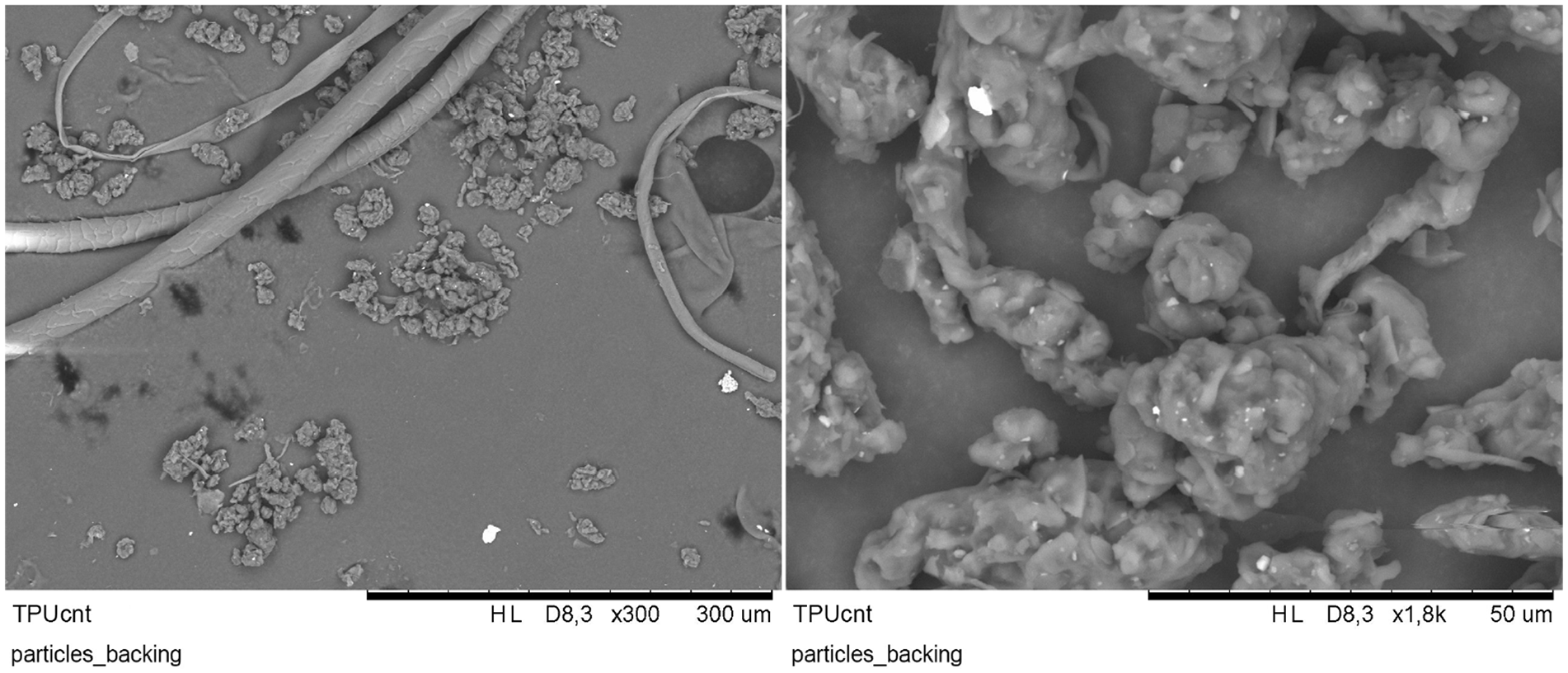
SEM pictures of particles shaken out of the backing felt (layer under abrasion fabric) of TPUcnt at different magnifications.
The influence of MWCNT inclusion on abrasion properties of printed FFF composites was investigated for a rigid compound of MWCNT with polyethylene terephthalate glycol. 37 Here, the MWCNT had little influence on the abrasion properties of the bulk material; however, the authors noted that microplastic release as well as the release of MWCNT from these particles is mainly governed by the matrix. In a study of TPU compounds by Shamsi et al., 38 nano-particles were found to improve abrasion resistance at low concentrations, but they had a negative effect on abrasion properties at higher concentrations. During abrasion testing, not only the hardness, but also the surface friction of a material influences the results. Due to the high filler content of TPUcnt (the highest CNT content in the study by Shamsi et al. 38 was 2.5 wt%), it is not only harder than its matrix material, but has a less tacky surface as well. This might play the decisive role in improving the abrasion resistance in our measurements.
Overall, the abrasion resistance of both TPUcnt and TC8OEX is acceptable for applications with a lower abrasion potential (easily achievable through choice of placement on a garment). For materials that are susceptible to abrasion, a similar strategy as in the case of chemical damage during washing could be useful: adding an electrically insulating, but more abrasion resistant layer around the conductive print materials could limit mechanical damage.
Conclusion
We showed the influence of different additives on the conductivity and mechanical properties of elastomer compounds printed using FFF. The following conclusions can be drawn:
Regarding the inclusion of short metal fibres as additives for improved conductivity in elastic materials for FFF, the trials were not successful. The amount of steel fibres that could be added to the matrix material was limited, as the stainless steel fibres made the material ‘scratchy’ on the surface, which is not acceptable for smart textile application, where the feel of a material is important, and print accuracy had to be sacrificed due to the bigger nozzle needed for the extrusion of these materials. In other applications, such as rigid conductive prints manufactured using FFF, the metal fibres could still be a viable option to increase conductivity.
FFF printing of short metal fibres poses no particular problem for the printing process, as long as a nozzle with a sufficiently large diameter is used.
A high amount of carbon-based fillers was utilized in conjunction with the steel fibres to achieve acceptable conductivity, but this resulted in increased brittleness of these materials.
Compounding of elastomers with MWCNT achieved the best electrical properties, but had a negative influence on mechanical properties and would limit the use of these materials severely.
A combination of MWCNT with CB did not improve the properties, as very high filler contents were necessary to achieve good conductivity.
Testing under repeated strain showed the materials’ highly complex behaviour under applied stress. As signal drift is a major concern for our samples, future measurements should be conducted with enough strain/relax cycle repetitions to achieve a stable signal; the measurement at 0% strain before testing cannot be used to make predictions about conductivity during use. Furthermore, our measurements show the usefulness of a quasi-static cyclic testing protocol, when compared to true dynamic testing, where the strain phase is immediately followed by a relaxation step. The clear appearance of a second peak during quasi-static testing cannot be ignored in real-life applications, while the shoulder peak visible in dynamic testing is easily overlooked.
TPUcnt had the most desirable properties for use as a conductive track at low strain, while TC8OEX provided much better properties for higher strain.
Under use, washing and abrasion would be a major concern and only TC8OEX showed promising results during washing tests, while both TPUcnt and TC8OEX had acceptable abrasion resistance.
The results further confirm that optimization of mechanic properties is extremely important for conductive materials.
The following improvements could be made to achieve better conductivity and use properties:
Encasing the conductive materials in insulating material with better use properties could offer a solution to insufficient washing and abrasion resitance, but increase production complexity. Furthermore, this strategy could also be used to abate possible microplastic concerns.
As extrusion settings during printing such as temperature affect the conductivity of the finished pieces, 31 different screw/nozzle configurations could also be used to conductivity after printing. Especially with conductive additives, where distribution of the conductive elements is crucial to achieving the desired conductive properties, shear during printing has not been a subject of major investigations. However, in the compounding and extrusion in traditional production machinery, different screw geometry and L/D-ratios are tailored to the material. Similar modifications on the miniaturized extrusion equipment on a 3D printer are obviously more intricate, but could provide better extrusion results.
Supplemental Material
sj-pdf-1-jef-10.1177_15589250241307016 – Supplemental material for Resistance of conductive FFF 3D printed compounds based on thermoplastic elastomers under repeated strain
Supplemental material, sj-pdf-1-jef-10.1177_15589250241307016 for Resistance of conductive FFF 3D printed compounds based on thermoplastic elastomers under repeated strain by Alexandra Glogowsky, Michael Korger, Sofie Huysman and Maike Rabe in Journal of Engineered Fibers and Fabrics
Footnotes
Declaration of conflicting interests
Funding
ORCID iDs
Supplemental material
References
Supplementary Material
Please find the following supplemental material available below.
For Open Access articles published under a Creative Commons License, all supplemental material carries the same license as the article it is associated with.
For non-Open Access articles published, all supplemental material carries a non-exclusive license, and permission requests for re-use of supplemental material or any part of supplemental material shall be sent directly to the copyright owner as specified in the copyright notice associated with the article.