
Abstract
Introduction
Compared with the conventional mechanical transmission, the electrical-drive transmission of the tracked vehicle has many advantages, such as continuously variable speed, excellent acceleration performance, and step-less steering. In the recent past, the designers of tracked vehicles have become more interested in electric transmission, thanks to the advancements in more compact electrical machines and power converters.
For the transmission of tracked vehicles, there are four main configurations. 1 Among them, the most commonly used configuration has two types: (1) independent driving with dual motors as shown in Figure 1 and (2) cross-drive electric transmission as shown in Figure 2. For example, the armored transport vehicle M113A3 is equipped dual motors that are driven independently. 2 In this form, two motors provide independent drive to each roller. The advantage of this configuration is that the motors can be arranged easily.

Independent driving with dual motors.

Cross-drive electric transmission.
It is well known that the tracked vehicles are steered by changing the relative track speed, that is, skid steering. When the tracked vehicles are steered, the speed and resistance of external track (high-speed side track) increase, while the speed and resistance of internal track (low-speed side track) decrease. Therefore, the motor needs to provide a larger power to external track while steering.
When the tracked vehicles are steered with a smaller radius, the external track provides the driving force, whereas the internal track provides the braking force, that is, a regenerative power will be generated at the internal track. For an independent driving with dual motors, the internal motor will work as a generator to absorb the regenerative power. The regenerated power during steering will be transmitted to the external motor in the form of electrical energy. If the internal track is braked (i.e. completely motionless), the output power of the internal track is equal to zero. In this case, the steering of the vehicle is completely driven by the external motor. Therefore, the traction motor should have larger power rating. If the regenerated power is transmitted to the external track through mechanical path, the required power rating of the motor will be greatly reduced. As a result, the motor will become more compact. To transfer the regenerated power, a middle power coupling mechanism is developed based on independent driving.1,3,4 A planetary power coupling mechanism with four ports is shown in Figure 3, in which two of the ports are rigidly connected to motors, while the other two ports are rigidly connected to the output shafts. The regenerated power can be transferred between the tracks through the power coupling mechanism.

Middle power coupling mechanism.
In fact, if the regenerated steering power is transmitted between the tracks, then the system efficiency will be improved. Assuming that

For the configuration shown in Figure 3, the net power absorbed by the two traction motors is lower than the power required by the two side tracks in most of the operating states. The relative output power of the two side tracks as a function of relative steering radius is shown in Figure 4. Let


Relative power of inputs and outputs.
Therefore, the following equation holds

The motor power of the configuration shown in Figure 3 is less than that of the configuration shown in Figure 1. As a result, the power loss of the configuration shown in Figure 3 is also smaller. This implies that the transmission with power coupling mechanism has higher system efficiency. Therefore, this article will focus on the study of the configuration synthesis of the transmission mechanism.
The design of a transmission involves not only finding the configuration that provides the correct output speed but also delivers necessary output torque. To achieve the skid steering, the two side tracks should be independent in their motion velocity and the force transmitted to the ground. Therefore, the two outputs also must be independent in their speed and torque. To address this, a system configuration synthesis method of transmission for electric-drive tracked vehicles is proposed in this article based on kinematics and statics.
For this purpose, an appropriate mathematical model is necessary for the conceptual design phase.
Graph representation
In 1960, the graph theory was used to express the abstract motion chain and mechanism in the literature. However, a careful definition of the graph is required because the kinematic equations for the mechanism are defined using the information displayed on it. The use of graphs for the analysis and development of equations involving planetary gear train (PGT) is common. A good survey and information on graph theory applications in PGTs are presented in Wojnarowski et al. 5 and Tsai. 6 In these analyses, the mechanisms are represented graphically. Researchers like Tsai et al. 7 have presented an analysis of kinematic relationships for planetary gear systems using block diagrams of planetary differential gears and compound planetary gear drives, together with the equations resulting from these diagrams. Other examples can be found in Rao and Rao, 8 Lang, 9 and Drewniak and Zawislak, 10 where the components of the trains (suns, carriers, rings, and planets) are represented by branches connecting the joints. JR Gomà Ayats et al. 11 proposed a method based on the utilization of hypergraphs, which provides a view into the analysis of complex mechanisms comprising PGTs and other variable or fixed transmissions.
In this article, a new graph model is proposed that provides a powerful assistance during the configuration design and can ease the analysis of kinematics and statics.
PGT
The types of mechanisms shown in Figure 5(a) with three main components are denoted as single PGT consists of a sun gear, a ring gear, a carrier, and several planets. The PGT is represented by


where

Planetary gear train: (a) simple PGT, (b) compound PGT with stepped planet, and (c) compound PGT with meshing planet pair.
In fact, there are many types of PGTs, and several more complex PGTs are shown in Figure 5. Among them, the expression that regulates the speed of all branches is always same. Again, the same representation is used, but
The graphical representation of a single PGT is shown in Figure 6, which is a star graph with three gray nodes and a white node. The three gray nodes represent the three links of the PGT as shown in Figure 6(b). The white node represents an interface between two or more (like in this case) gray nodes, that is, a kinematic connection (like a mesh between a pair of cogwheels) between two or more mechanical elements.

(a) Planetary gear train and (b) graph representation.
Speed conversion mechanism
The speed conversion mechanism is defined as a generalized single-input single-output transmission mechanism, and its function is to change the speed and torque. Without considering the power loss, the speed and torque relationship between input and output are as follows


where
Speed conversion mechanism has many forms, for example, a gear pair, as shown in Figure 7(a) and (b). The graph representation of the gear pair is a path with two gray nodes and one white node as shown in Figure 7(c). The two gray nodes represent the input and output, respectively.

(a and b) Gear pair and (c) graph representation.
If the rotation of any link is prevented, then the PGT would become a speed conversion mechanism, which can be represented by deleting the corresponding nodes as shown in Figure 8.

Braking and graph representation: (a) ring gear braked and (b) carrier braked.
Fixed connection
If serval links are rigidly connected as a member, then the corresponding graph can be expressed by merging serval nodes as shown in Figure 9. In such case, all links that are rigidly connected must satisfy the speed and torque constraint equations as follows


where

Fixed connection (a) with input and output and (b) between links.
Degree of freedom
The (operating) degree of freedom (DOF) of a system is defined as the number of independently and arbitrarily presentable parameters or states for a particular operating condition. According to Mueller,
12
the operating DOF of a transmission is equal to the sum of its kinematic and static DOF. For the transmission, the presentable speeds and torques exist, so the kinematic DOF and static DOF are actually speed DOF and torque DOF, respectively. In this article,
Looking at the number of independent variables to solve the system of equations (4) and (5) (
From the viewpoint of degrees of freedom, since the two outputs of the transmission must be independent both in their speed and torque, the total amount of speed DOF and torque DOF should be greater than or equal to 2. Therefore, the following conclusions hold.
Conclusion 1
For the transmission of tracked vehicles, the reasonable configuration must satisfy the following two conditions:
The two outputs should be independent both in their speed and torque.
Both the speed DOF and torque DOF should be greater than or equal to 2.
Next, the speed DOF and torque DOF of the transmission are analyzed, and the calculation formulas are derived.
Consider a transmission mechanism which contains


The rigid connection between the links reduces the DOF. Let

According to equations (8) and (9), if

From equations (12) and (13), the reduction in torque DOF is given as

For any transmission, the speed DOF and the torque DOF can be calculated as follows


Therefore, the speed DOF and torque DOF can be obtained as follows


The following equation is valid from equations (17) and (18)

Configuration synthesis
In this section, a configuration synthesis method for the transmission of electric-drive-tracked vehicles is proposed. The configuration synthesis process is shown in Figure 10. In this article,

Configuration synthesis process.
Rigid interconnection between PGTs
First, the number of rigid interconnections between PGTs is determined. According to equation (17), the number of fixed interconnections can be calculated as follows

For example, a fixed interconnection scheme with

Fixed connection between PGTs.
Synthesis of inputs and outputs
For the tracked vehicles, the number of outputs

Configuration with

Configuration with

Configuration with
Synthesis of speed conversion mechanism
The function of speed converter mechanism is to change the speed and torque of the output such that the kinematic and static requirements are met. For example, the configuration shown in Figure 15 can be obtained by adding speed conversion mechanism from the configuration shown in Figure 12. The corresponding graph operation can be expressed by inserting a node of degree two between the output and the link of PGTs.

Synthesis of speed conversion mechanism.
Symmetry analysis
In general, the transmission mechanism should be designed to be symmetrical. The symmetrical structure has several advantages, for example, good kinematic and dynamic performance. From the viewpoint of graph theory, the symmetry is defined as (1) the existence of an automorphism as follows

And (2) the two output shafts change position, that is,
Let

Then, the configuration is symmetrical. This method is convenient to verify the symmetrical nature of transmission mechanism using a computer. Also, the method can be applied to other types of mechanism.
Necessary conditions to realize skid steering
According to conclusion 1, the condition to achieve the skid steering is that the two outputs of the transmission mechanism should be independent in their speed and torque. From the viewpoint of the graph, if there exists a path between the two outputs that does not contains one white node of degree 3 (PGT), then it has
Conclusion 2
For the transmission mechanism of tracked vehicles, the necessary condition to achieve the skid steering is as follows
Any path between the two outputs contains at least one white node of degree 3.
Any path between the two outputs contains at least one gray node of degree more than 2.
Conclusion 2 provides the necessary condition to achieve the skid steering as shown in Figure 16. However, this condition is not sufficient.

Path between output 1 and output 2.
For example, a transmission mechanism is considered in Figure 17. The kinematic constraint equations for this case are as follows
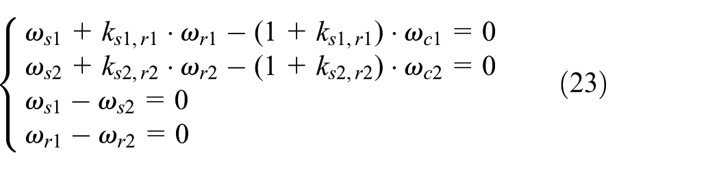

Transmission mechanism.
If
Therefore, further kinematic and static analysis must be carried out to determine whether the mechanism can achieve the skid steering.
Parameter determination
After a configuration has been generated, the immediate task is to determine the characteristic parameters of the PGT and the speed ratio of the speed conversion mechanisms. Parameters should be determined according to the following steps. At first, the feasibility of the configuration is examined to ensure the possibility of skid steering. Second, the parameters, which can be set by the designer, should be made to vary within the admissible range and component-imposed constraints (e.g. considering the maximum speeds of the generator and the motor). The third step is to make sure that the transmission should have the highest possible transmission efficiency.
Kinematic and static analysis
To determine the possibility of skid steering for the transmission mechanism, it is necessary to carry out the kinematic and static analyses. Obviously, the speed and torque constraint equations are all homogenously linear. Next step is to write the speed and torque constraint equations and obtain the linear system of equations, which can be written in matrix form as follows


where


where


In this case, the transmission cannot achieve the skid steering. Here,
According to linear algebra, the following conditions for equations (28) and (29) can be established


where
Power flow and efficiency analysis
According to equations (24) and (25), it is possible to calculate the speed and torque of all links. Furthermore, the power flow and efficiency of the transmission can be analyzed. The efficiency depends on the power loss of the transmission system, which consists of two parts: the power loss in the motor and the power loss in the mechanical transmission.
According to the number of DOF, the transmission mechanism can be divided into two types. The first type is that
For the first type, the output speed and torque are uniquely determined by the speed and torque of outputs. Therefore, the efficiency of transmission depends on the parameters of the system. For the second type, the speed and torque of input motors are not uniquely determined by the output speed and torque, but infinite. Therefore, the efficiency of the system not only depends on the parameters of the system but also the speed or torque distribution of motors.
A transmission mechanism with

where

Two types of transmission: (a)
A transmission mechanism with

For this configuration, the parameters should be determined based on its performance under the optimal allocation of motor torque.
Results
Using the configuration synthesis method proposed in this article, many configurations can be obtained, which can be classified according to the speed DOF and the torque DOF. Figure 19 shows several configurations with two PGTs, and Figure 20 shows several configurations with three PGTs. Following are some of the inferences.

Configuration with two PGTs: (a)

Configuration with three PGTs: (a)
Conclusion
In this article, a graph-based configuration synthesis method of electric-drive transmission for tracked vehicles was presented. First, a new graph theory model is proposed to represent the transmission mechanism, which makes the complex system much easier to understand. The abstraction representation of the mechanism in the form of a simple graph assists the designer during the conceptual design stage. Second, a method to design the configuration is proposed considering the kinematic and static aspects of the transmission, in which the speed DOF and torque DOF are the constraints. Also, the formula to calculate the speed DOF and torque DOF are derived. Based on the graph theory model, the necessary conditions for the tracked vehicles to achieve the skid steering are obtained. The results of this article can be used to design and analyze the transmission mechanism of tracked vehicles.
In future, the relationship between the topology and performance of the configuration will be further studied, which will provide the theoretical basis for the design and analysis of the transmission mechanism.