The sine movable tooth drive has small radial dimension such that the heat, caused by friction, becomes an important factor in deciding its load-carrying ability. It is important to determine the amount of tooth lubrication in order to reduce the heat caused by the friction. This study provides equations for the meshing performance and provides the forces for the sine movable tooth drive. Using these equations, the minimum oil film thickness for the drive system is investigated. Results show that the minimum film thickness between the movable tooth and input shaft or shell changes periodically along the input shaft rotation angle. A large movable tooth radius and a movable tooth rotation radius could increase the film thickness between the movable tooth and the input shaft or the shell. In addition, a large speed ratio could increase the film thickness between the movable tooth and the input shaft, but this would also decrease the film thickness between the movable tooth and the shell. A large sine amplitude could increase the film thickness between the movable tooth and the input shaft, but this does not change the film thickness between the movable tooth and the shell. Under normal operation speeds, the hydrodynamic lubrication condition occurs between the movable tooth and the input shaft, and the partial membrane hydrodynamic state occurs between the movable tooth and the shell.
Movable tooth drives have many advantages, including the lightweight, large transmission efficiency, a wide range of transmission ratio, and a high load-carrying ability. Therefore, the drives can be used in many fields, including aerospace, precision instruments, and oil mines. Keith1 and Imase2 proposed the ball-rolling-type gear drive system. Terada et al.3–6 investigated the motion principle, strength, and efficiency of the cycloid ball reducers. Li et al.7 used the gray-relational theory to analyze the fault of the sine oscillating tooth drive. Terada and Imase8 and Terada9 proposed a two-step ball tooth drive and calculated its profile. Liang et al.10 did the tooth profile analysis and strength calculation of the swing movable tooth drive. Sapsalev11 adjusted the movable tooth drive and used it in an electric drive system. Nam et al.12 designed a ball tooth thin plate-type drive to power the robots. Nishibe et al.13 proposed an eccentric movable tooth drive for driving the robot arm. Liang and Xu14,15 developed an electromagnetic harmonic movable tooth drive.
In drive systems, meshing friction between two mesh pairs could generate heat and increase the temperature in the mesh pairs.16 This process could greatly affect the mechanical properties of the mesh elements such that the stress distribution changes within the gear/shaft assembly.17 As its operating load and speed increase, the effects of the meshing friction heat on the operating performance of the mesh pairs become more significant.18 In addition, frictional heat has much stronger effects on the operating performance of a small size drive system versus a normal size drive system.19
Among movable tooth drives, the sine movable tooth drive has the smallest radial dimension. The drive system includes following main elements: input shaft, shell, movable teeth, and the output shaft (see Figure 1). When decreasing the drive size, friction heat becomes more influential for its load-carrying ability. When reducing friction heat, lubrication plays an important part. However, the lubrication problem for the sine movable tooth drive has not yet been studied extensively.
3D model of the sine movable tooth drive.
In this article, the equations of the meshing performance and forces for the sine movable tooth drive are deduced. Using these equations, the elastic hydrodynamic lubrication (EHL) minimum oil film thickness for the drive system is investigated. Results show that the EHL minimum film thickness between the movable tooth and input shaft tooth or shell tooth changes periodically along the input shaft rotation angles. The sine amplitude, speed ratio, movable tooth radius, and its rotation radius have an effect on the oil film thickness between the movable tooth and the input shaft or shell. To increase the film thickness, the sine amplitude, movable tooth radius, rotation radius, and speed ratio must be selected carefully. This study is useful for the design and efficiency prediction of the sine movable tooth drive system.
Mesh analysis
The coordinate systems for the mesh analysis of the drive system are shown in Figure 2. Here, the coordinate system is attached to the input shaft, is attached to the guide frame, attached to the fixed shell, and attached to the movable tooth. φ denotes angle between coordinates σ3 and σ. φ1 denotes angle between coordinates σ2 and σ1. φ3 denotes angle between coordinates σ2 and σ3. k-axis is the rotating axis of the input and output shafts. Relationship between rotation angles of the different elements is
where Z1 is the period number of track on the input shaft and Z3 is the period number of track on the shell.
Coordinate systems for the drive system: (a) drive system and (b) movable tooth.
The coordinate transformation matrix from the coordinate system to the system is given as
The coordinate transformation matrix from the coordinate system to the system is
The coordinate transformation matrix from the coordinate system to the system is
where , it is axial displacement of the movable tooth; A is the sine track amplitude. The surface of movable tooth (a ball) in coordinate system is defined by (see Figure 2(b))
where r is the radius of the movable tooth, u and v are the ball surface parameters. From equation (5), we can obtain
The normal vector of the movable tooth surface in coordinate system is
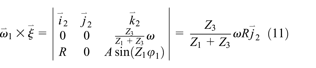
Using meshing theory, the relative velocity between the movable tooth and input shaft tooth can be calculated as
where is the vector between origins of coordinates σ0 and σ2, , and
, where is angle velocity between the movable tooth and guide frame ; is angle velocity between the input shaft and guide frame ; ω is the angle velocity of the input shaft. Thus
In a same manner as equation (15), the velocity sum of the movable tooth and shell tooth can be calculated as
where
Thus, the average velocity in the normal line direction of the contact line between the movable tooth and input shaft tooth or shell tooth is
where
The induced normal curvature kv1 between the movable tooth ball and input shaft tooth can be given as
where and .
Kv0 and Gv0 are the normal curvature and geodesic torsion at contact point on the movable tooth ball in the direction, respectively (Kv0 = 1/r, Gv0 = 0). Substituting related parameters into equation (18), the induced normal curvature kv1 between the movable tooth ball and input shaft tooth can be given as
where
In a same manner as equation (19), the induced normal curvature equation between the movable tooth ball and shell tooth can be given as
where
As the induced normal curvature kv1 or kv3 increases, the film thickness of the drive system will be reduced significantly. Similarly, the angle equation of the relative velocity vector to the contact line is obtained
where Ѳv1 and Ѳv3 are the angles for movable tooth and input shaft or shell, respectively.
Load and oil film thickness
Neglecting friction force and gravity, forces on a movable tooth and related elements are shown in Figure 3. F1i denotes the force between the movable tooth and the outer track on the input shaft, and αn1i denotes its directional angle. F3i denotes the force between the movable tooth and the inner track on the shell, and αn3i denotes its directional angle. F2i denotes the force between the ball and guide slots. u1i and u3i denote angles between forces F1i or F3i and plane xoy, respectively.
Forces on a movable tooth and related elements: (a) movable tooth, (b) input shaft, and (c) shell.
From force balance relationship of the movable tooth, we can obtain
In equation (23), there are five unknown parameters. So, two other equations should be given. Let F1ix and F1iyz denote radial component and normal one of F1i, respectively; Δs denote the tangent displacement of the balls under a given torque; the deformation coordination equation of the mesh pair is
where , . Rj (j = 1, 3) is the motion radius of the sine tracks on the input shaft and shell, respectively. From torque balance relation of the input shaft, we can give
where T1 is the input torque, equal to motor torque Tem. z2 is the movable tooth number of the drive system. From the geometric relation of the drive system, we know
where r′ is the radius of the sine ball track, and r is the radius of movable tooth (ball). From equations (23)–(26), we can give
Here, . Using equation (27), five unknown parameters can be resolved. Thus, the forces in the drive system can be determined.
From Dowson–Higginson’ s equation, the minimum oil film thickness Hmin between the movable tooth and input shaft tooth or shell tooth is
where α is the pressure viscosity coefficient; E′ is the effective elastic modulus; Rs is the effective curvature radius, ; η0 is kinematic viscosity of the lubricant; Ui is the entrainment velocity of the two tooth surfaces in mesh; Fni is forces between movable tooth and related elements (n = 1 or 3); and li is length of contact line, it is equal to be
Combining equations (17), (19), (20), (27) and (29) with equation (28), the minimum film thickness Hmin between the movable tooth and input shaft tooth or shell tooth can be given.
Results and conclusion
The changes of the induced normal along with the drive parameters were investigated using the aforementioned equations (see Figure 4). Parameters of a sample drive system are shown in Table 1. The results of the study show the following:
Changes of the induced normal curvature along with drive parameters: (a) A changes, (b) R changes, (c) r changes, (d) A changes, (e) R changes, and (f) r changes.
Main parameters for the sine movable tooth drive.
Speed ratio, i
6
Motion radius of the sine ball track, R (mm)
25.5
Ball radius, r (mm)
4.0
Track radius, r′ (mm)
4.4
Track amplitude, A (mm)
3.6
Period number of track, Z1
1
Number of movable tooth, Z2
5
Period number of track, Z3
5
The induced normal curvature kv1 between the movable tooth and the input shaft changes slightly at different meshing positions. As the sine amplitude A increases, the induced normal curvature kv1 increases. It should be noted that increase in the amplitude A influences the homogeneity of the induced normal curvature kv1 along the rotation angles of the input shaft. As the sine amplitude A increases, the homogeneity of the induced normal curvature kv1 along the rotation angles is decreased. As the radius R increases, the induced normal curvature kv1 increases as well. As the radius r increases, the induced normal curvature kv1 decreases. There are no effects of the radii R and r on the distribution of the induced normal curvature kv1 along the rotation angles.
The induced normal curvature kv3 between the movable tooth and shell changes is obvious at different meshing positions. As the sine amplitude A increases, the induced normal curvature kv3 increases as well. The increase in the amplitude A influences the homogeneity of the induced normal curvature kv3 and the rotation angles as well. As the sine amplitude A increases, the homogeneity of the induced normal curvature kv3 along the rotation angles also decreases. As the radius r increases, the induced normal curvature kv3 decreases significantly. The radius r has little effect on the distribution of the induced normal curvature kv3 along rotation angles. As the radius R increases, the induced normal curvature kv3 increases near the meshing start and end points, but it hardly changes near the midpoint of the meshing area. Therefore, the homogeneity of the induced normal curvature kv3 along the rotation angles increases when increasing the radius R.
The induced normal curvature kv1 between the movable tooth and input shaft is close to the induced normal curvature kv3 between the movable tooth and shell. For the small sine amplitude A, the distribution of the induced normal curvature kv1 along the rotation angles is even. The distribution of the induced normal curvature kv3 along the rotation angles changes periodically. The changes are quite small and its fluctuation ratio is about 2%.
Essentially, the distribution of the induced normal curvatures kv1 and kv3 along the rotation angle positions is relatively even. To reduce the induced normal curvatures, a large r and small R and A should be used. Here, we investigate the changes of the angle regarding the position of the relative velocity vector to the contact line (see Tables 2 and 3). In Tables 2 and 3, f1 denotes the rotation angle of the input shaft, and n represents the different points on the contact line of the movable tooth.
θv1 changes along with ball tooth position parameter γ and rotation angle f1 (A = 3.6 mm, R = 25.5 mm, r = 4 mm, Z1 = 1, and Z3 = 5).
φ1 (°)
v (°)
θv1 (°)
0
0
88.9219
30
88.9026
60
88.8446
90
88.7563
30
0
89.0624
30
89.0455
60
88.9948
90
88.9176
45
0
89.2311
30
89.2172
60
89.1754
90
89.1183
60
0
89.4540
30
89.4441
60
89.4142
90
89.3688
θv3 changes along with ball tooth position parameter γ (A = 3.6 mm, R = 25.5 mm, r = 4 mm, Z1 = 1, and Z3 = 5).
φ3
v
θv3
0°
0°
86.8595
30°
86.7396
60°
86.3684
90°
85.7744
30°
0°
87.1009
30°
86.9826
60°
86.6125
90°
86.0080
45°
0°
87.4657
30°
87.3546
60°
87.0030
90°
86.4145
60°
0°
88.0717
30°
87.9804
60°
87.6874
90°
87.1825
From Tables 2 and 3, we know that angle shows different results at the various rotation angle positions. From 0° to 60°, the angle value gradually increases. For a given rotation angle, the angle is different at different points on the contact line. From the point on one end (n = 0°) to the other end (n = 90°) along the contact circle arc, the value of the angle gradually reduces. However, the differences between the different values are very small. Therefore, the angle can be considered as a constant. These results offer understanding of the contact stresses and the EHL for the drive system.
The angle of the relative velocity vector to the contact line is close to 90°. It shows that the drive system has a favorable position of the instantaneous contact lines and a high load-carrying capacity of the oil film.
Using equation (27), forces in the drive system are calculated (see Figure 5). Here, the output torque Tem of the motor is 0.2 N m.
Forces and their changes along with drive parameters: (a) forces on movable tooth, (b) F3i changes along with A, and (c) F3i changes along with R.
Figure 5 shows that the force F3i between the movable tooth and the shell is the largest. The force F2i between the ball and the guide slot is smaller than F1i between the ball and the input shaft. These forces are distributed along the rotation angle f of the input shaft periodically. The fluctuation angle period is 6π/5 (it can be calculated as ).
Forces between the movable tooth and the other elements decrease when the sine amplitude A increases because the pressure angle between the movable tooth and other elements reduces when the sine amplitude A increases. Forces between the movable tooth and other elements decrease when increasing the radius R because the force arm increases when increasing the radius R.
Using the aforementioned equations, the minimum film thickness Hmin between the movable tooth and input shaft tooth or shell tooth is calculated (see Figures 6–8 and Table 4). Here, n = 2800 r/min, α = 2.1 × 10⁻⁸ m2/N, η0 = 20 × 10–3 Pa s, and E′= 2.3 × 10¹¹ Pa. The results show the following:
The minimum film thickness Hmin between the movable tooth and the input shaft tooth or the shell tooth changes periodically along the input shaft rotation angles. Its angle period is also 6π/5 as well, which is mainly caused by the force fluctuation in the drive system. It should be noted that the film thickness fluctuation between the movable tooth and the input shaft tooth is much smaller than that between the movable tooth and the shell tooth.
Hmin between the movable tooth and the input shaft or shell.
Effects of the drive parameters on the film thickness between movable tooth and input shaft: (a) A changes, (b) R changes, (c) r changes, and (d) i changes.
Effects of the drive parameters on the film thickness between movable tooth and shell: (a) A changes, (b) R changes, (c) r changes, and (d) i changes.
Hmin between contact pairs for various input shaft speeds.
n (r/min)
Hmin1 (μm)
Hmin3 (μm)
750
0.711 ~ 0.726
0.127 ~ 0.263
1400
1.194 ~ 1.219
0.213 ~ 0.441
2800
2.123 ~ 2.167
0.379 ~ 0.784
5400
3.661 ~ 3.737
0.653 ~ 1.353
The minimum film thickness Hmin between the movable tooth and the input shaft tooth is about 1.940 ∼ 1.980 μm, which is much larger than those between the movable tooth and the shell tooth (0.346 ∼ 0.717 μm). This is mainly caused by the different relative velocities between the two contact pairs.
The rough surface of the element teeth is approximately 0.2 μm, while the ratio of the film thickness to the composite roughness between the movable tooth and the input shaft tooth is above 3, which causes the hydrodynamic lubrication condition. The ratio of film thickness to composite roughness between the movable tooth and the shell tooth is between 1 and 3, such that a partial membrane hydrodynamic state occurs:
2. As the sine amplitude A increases, the film thickness Hmin between the movable tooth and the input shaft increases. Meanwhile, the fluctuation of the film thickness Hmin along the input shaft rotation angle increases as well. When the amplitude value A changes from 2.6 to 4.6 mm, the film thickness increases by about 1.2 times. As the radius R increases, the film thickness Hmin between the movable tooth and the input shaft increases as well. However, it does not closely influence the fluctuation of the film thickness along the input shaft rotation angle. The movable tooth radius r has the most obvious effects on the film thickness Hmin between the movable tooth and the input shaft. When the radius r changes from 3 to 5 mm, the film thickness increases by about 1.4 times. As the speed ratio i increases, the film thickness Hmin between the movable tooth and the input shaft increases as well. When the speed ratio i changes from 5 to 7, the film thickness increases by about 1.1 times. It should be noted that the speed ratio i has an effect on the fluctuation period of the thickness along the input shaft rotation angle.
3. As the sine amplitude A increases, the film thickness Hmin between the movable tooth and the shell changes. Near the 3π/5 rotation angle of the input shaft, the film thickness Hmin increases with the sine amplitude A. However, the film thickness Hmin decreases significantly with the sine amplitude A for other rotation angle positions. As the sine amplitude A increases, the fluctuation of the film thickness Hmin along the input shaft rotation angle increases. When the amplitude value A changes from 2.6 to 4.6 mm, the fluctuation of the film thickness Hmin increases from about 15% to about 65%. As the radius R increases, the film thickness Hmin between the movable tooth and the shell increases as well. It does not closely influence the fluctuation of the film thickness along the input shaft rotation angle either. The movable tooth radius r also has an effect on the film thickness Hmin between the movable tooth and the shell. When the radius r increases, the film thickness increases. Near the 3π/5 rotation angle of the input shaft, the film thickness Hmin increases with the sine amplitude A more significantly than at other rotation angles. As the speed ratio i increases, the film thickness Hmin between the movable tooth and the shell decreases. Meanwhile, the fluctuation of the film thickness along the input shaft rotation angle increases when the speed ratio i increases. The fluctuation period of the thickness along the input shaft rotation angle also changes when the speed ratio i is changed. The wave peaks of the film thickness are reduced slightly, but its troughs of wave are clearly reduced when the speed ratio i is increased.
4. The minimum film thickness Hmin between the movable tooth and the input shaft tooth or shell tooth increases with the speed. As the surface roughness of the element teeth is 0.2 μm, the ratio of the film thickness to composite roughness between the movable tooth and the input shaft tooth is about 2.5, 4.2, 7.4, and 13 at n = 750, 1400, 2800, and 5400 r/min. This shows the hydrodynamic lubrication condition between the movable tooth and the input shaft tooth occurs for these speeds. The ratio of film thickness to composite roughness between the movable tooth and the shell is about 0.7, 1.1, 2.1 and 4.5 at n = 750, 1400, 2800, and 5400 r/min. This shows that hydrodynamic lubrication condition between the movable tooth and the shell tooth occurs for higher speeds (5400 r/min). Here, the partial membrane hydrodynamic state occurs for normal speeds (n = 750, 1400, and 2800 r/min).
Conclusion
In this article, equations of the meshing performance and forces for the sine movable tooth drive are deduced. Using these equations, the minimum oil film thickness for the drive system is investigated. The results show the following:
The minimum film thickness between the movable tooth and the input shaft tooth or the shell tooth changes periodically along the input shaft rotation angles. This is mainly caused by a force fluctuation in the drive system.
The sine amplitude, speed ratio, movable tooth radius, and its rotation radius have an effect on the film thickness between the movable tooth and the input shaft. To increase the film thickness, a large sine amplitude, a movable tooth radius and its rotation radius, and a speed ratio should be used.
To increase the film thickness between the movable tooth and the shell, a large movable tooth radius and its rotation radius, and a small speed ratio should be used.
For given operation parameters, the hydrodynamic lubrication condition between the movable tooth and the input shaft tooth occurs, and between the movable tooth and the shell tooth, the partial membrane hydrodynamic state occurs for normal speed.
The future work will focus on effects of the lubrication condition on the friction heat and temperature increases of the drive system.
Footnotes
Handling Editor: ZW Zhong
Declaration of conflicting interests
The author(s) declared no potential conflicts of interest with respect to the research,authorship,and/or publication of this article.
Funding
The author(s) disclosed receipt of the following financial support for the research,authorship,and/or publication of this article: This project was supported by the Hebei Province Natural Science Foundation in China (No. E2017203021).
ImaseK. Ball-rolling type torque transmission device. US5683323A Patent, 1997.
3.
TeradaHMakinoHImaseK. Fundamental analysis of cycloid ball reducer (1st report): motion principle. JSPE1988; 12: 2101–2106.
4.
TeradaHMakinoHImaseK. Fundamental analysis of cycloid ball reducer (2nd report): radius of curvature and pressure angle. JSPE1990; 56: 751–756.
5.
TeradaHMakinoHImaseK. Fundamental analysis of cycloid ball reducer (3rd report): strength design. JSPE1995; 12: 1705–1709.
6.
TeradaHMakinoHImaseK. Fundamental analysis of cycloid ball reducer (4th report): efficiency analysis and development of the Oldham’s type output mechanism. JSPE1997; 6: 834–838.
7.
LiGYuGSunY. Application of grey-relational theory in fault tree analysis of miniature sine oscillating tooth gear drive. Chin J Constr Mach2006; 4: 127–132.
8.
TeradaHImaseK. Fundamental analysis of a cycloid ball reducer (5th report): development of a two stage type reduction mechanism. JSPE2009; 12: 1418–1422.
9.
TeradaH. The development of gearless reducers with rolling balls. J Mech Sci Technol2010; 24: 189–195.
10.
LiangSFuBWangD. Tooth profile synthesis and strength computation of swing movable teeth drives. Key Eng Mater2011; 474–476: 162–167.
11.
SapsalevAV. Optimizing cyclic gearless electric drives with a reduced-speed section. New York: Allerton Press, 2012, pp.438–443.
12.
NamWShinJOhS. Design of thin plate-type speed reducers using balls for robots. J Mech Sci Technol2013; 27: 519–524.
13.
NishibeSMitsufujiSNishitaniY. Eccentric oscillating reduction gear for joint drive of robot. JP2014161952A Patent, 2014.
14.
LiangYXuL. Free vibration for an electromagnetic harmonic movable tooth drive system. Open Mech Eng J2015; 9: 15–21.
15.
XuLLiangY. Torque for an electromagnetic harmonic movable tooth drive system. Mech Mach Theory2016; 98: 190–198.
16.
WangYTangWChenYet al. Investigation into the meshing friction heat generation and transient thermal characteristics of spiral bevel gears. Appl Therm Eng2017; 119: 245–253.
17.
GolbakhshiHNamjooM. Thermo-structural analysis on evaluating effects of friction and transient heat transfer on performance of gears in high-precision assemblies. J Cent South Univ2017; 24: 71–80.
18.
WangYShaoJWangXet al. Effect of load and speed on warship power rear drive system helical gear anti-scuffing properties in thermal elasto-hydrodynamic lubrication. Adv Mech Eng2017; 9: 1687814016684703.
19.
KimHSKimCKwakSH. The strength and frictional heat of the small high-speed gears in a medical hand-piece. In: Proceedings of the international conference on mechanics and materials engineering, Xi’an, China, 12–13 April 2014, pp.205–209. USA: Destech Publications, Inc.