
Abstract
Introduction
Since the opening of China’s first straddle-type monorail line in the mountain city of Chongqing in November 2004, its outstanding advantages, including low cost, strong climbing ability, and small turning radius, have not only made urban traffic planning spatial and diversified but also effectively improved the way people travel.1–3 However, in the past decade of operation, the Chongqing straddle-type monorail train has experienced abnormal wear of its running wheel tires, which affected driving safety, increased operating cost, and polluted the environment. More seriously, this has become the main obstacle to the further promotion of straddle-type monorail traffic.4,5
The configuration of straddle-type monorail resembles a traditional railway vehicle, but rubber tires similar to automobile tires are used for the running, guiding, and stabilizing wheels in the running system. The running wheels without differentials or alignment parameters contact with the upper surface of the track beam to provide driving and braking force. The guiding and stabilizing wheels are clamped on the upper side and lower side of the track separately to offer steering torque and additional anti-overturning moment for the bogie. All the wheels are rigidly connected to the bogie frame, forming an over-constrained wheel train structure. Thus, the running wheel tires will be subjected to complex coupled forces and moments when the train turns a corner, which may cause abnormal wear of the tires.
Compared with traditional railway vehicles and automobiles, the research on tire wear of straddle monorail-type vehicles is yet to receive extensive attention. Most of the research on straddle-type monorail traffic focuses on the analysis of vehicle-bridge coupled dynamic response and vehicle ride comfort.6–12 C Lee and colleagues6–9 established the vehicle-bridge coupled vibration model of straddle-type monorail which is applicable in studying the vehicle ride comfort and the dynamic response of different bridge structures. However, each tire in the above vehicle model was replaced by a unidirectional linear spring and damper, which could not accurately reflect the lateral vibration of the running wheels and it is therefore necessary to improve or build a new tire model as the lateral vibration characteristics are key causes resulting in the abnormal wear of the running wheel tires. 13 He 14 proposed a method to reduce the wear of running wheel tires by focusing on tire inflation pressure and installation accuracy of track beams, without revealing its mechanism. Liu and Gao 15 developed an intelligent detection and management system for running wheel tires, which can extend the service life of tires to a certain extent, but it did not solve the tire wear problem from the source. Du and colleagues16,17 used finite element method to analyze the wear of running wheel tires under different operating conditions, and reproduced the phenomenon of eccentric wear of running wheel tires without sufficient mechanism explanation. Thus, further research is still needed.
In this research, a 15-DOF (degree of freedom) vehicle spatial dynamics model with multi-directional linear elastic tire models was established. The forces and moments on each running wheel tire in the bogie was obtained with consideration to preloading of guiding and stabilizing wheels, super-elevation in the curve section of track beam, and centrifugal force. The finite element model of running wheel tire was then built to reveal the wear state by analyzing the contact pressure distribution, shear stress distribution, lateral and longitudinal slip, and other field output under the combined action of different slip angle, roll angle, and slip rate, which provides guidance for improving the abnormal wear.
Materials and methods
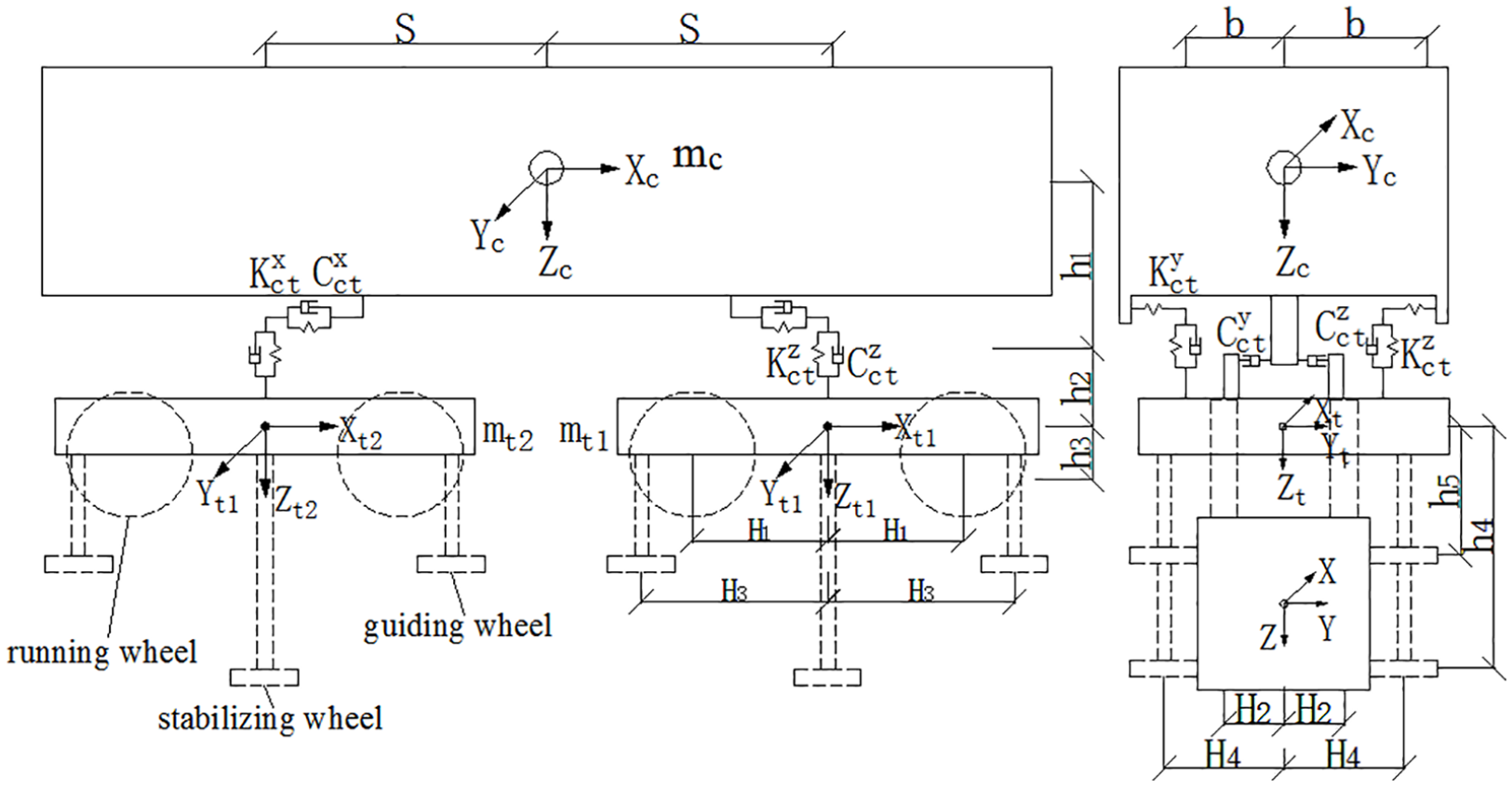
Straddle-type monorail transit system is mainly composed of vehicle system and track structures, as shown in Figure 1. The vehicle system mainly includes one car body, two bogies, and other attachments. The car body and bogies are connected by a central suspension system composed of air springs, rubber traction stacks, and shock absorbers. Each bogie has two horizontal rigid axles equipped with four running wheel tires and six vertical rigid axles with four guiding wheel tires and two stabilizing wheel tires, as shown in Figure 2. The track beams can be regarded as rigid structures when studying the wear of running wheel tires as the resonance of vehicle-bridge system is a small probability event. 18 When a straddle-type monorail train travels on straight lines, the running wheel tires wear out normally except under strong crosswind or other extreme forces. When it runs on a curved section, the running wheel tires are subjected to large lateral forces and abnormal wear may occur. The smaller the curvature radius of the curve, the more serious the abnormal wear may be. This study, therefore, focuses on the characteristics of vehicles driving on curved sections.

Straddle-type monorail system.

Wheel-track system.
Dynamic model of straddle-type monorail vehicle
Coordinate system
When the straddle-type monorail vehicle runs on a curved section, its moving direction changes in real time, therefore, the vehicle flow coordinate system needs to be established. As shown in Figure 3, all the coordinate systems follow the right-hand principle.

Vehicle flow coordinate system.
Vehicle model
Straddle-type monorail vehicle is mainly composed of one vehicle body, two bogies, and corresponding connectors. The body and bogie can be regarded as a symmetrical rigid body with six DOF. Since the influence of the telescopic motion on the vehicle vibration can be neglected, the DOF of the vehicle model can be reduced to 15, as shown in Table 1. The elastic elements of the secondary suspension in the straddle monorail vehicle are symmetrically arranged, as shown in Figure 4 (the parameters used and not explained in the main text are defined in Appendix 1).
Vehicle freedom.

Model of straddle monorail vehicle.
Tire model
Assuming that each tire is always in contact with the track beam surface when the straddle-type monorail turns a corner and vibrates slightly in the equilibrium position, the running wheel tires will be subjected to the coupling forces from the guiding wheel and stabilizing wheel tires, resulting in both vertical and lateral deformation. For this reason, it is necessary to take lateral characteristics of the tire into consideration when studying tire wear. The tire model of the running wheel and horizontal wheel (guiding wheel and stabilizing wheel) is shown in Figure 5.
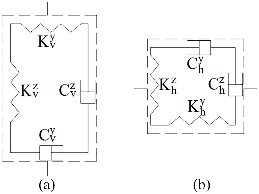
Tire model: (a) running wheel and (b) guiding and stabilizing wheel.
Differential equations of motion
For a complex vibration system, the Lagrange method is efficient and convenient to derive the differential equations of motion, as it is relatively easy to calculate the total kinetic energy, potential energy, and damping dissipation energy of the system.
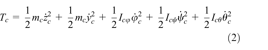
Since the mass of each tire is negligible relative to the vehicle body and bogie, the total kinetic energy of the system

where

The total potential energy of the system can be expressed as the sum of the secondary suspension potential energy

The coupling effect of the longitudinal, lateral, and vertical motion of the vehicle body and the bogies can be neglected, thus, the secondary suspension potential energy can be expressed as

where the longitudinal, lateral, and vertical potential energy is shown in formulae (6), (7), and (8), respectively


The potential energy stored in the primary suspension can then be expressed as

While


where
The equation structure of the system’s total damping dissipation energy

where
Generalized force
When the Straddle-type monorail turns a corner, it will be affected by centrifugal force which reduces ride comfort; super-elevation is then set in on the upper surface of the track beams to offset partial centrifugal force, as shown in Figure 6. The super-elevation angle of the main section of curved track beam

Track beam super-elevation.
There is a transition section between the main section of the curved track beam and the straight section, so the super-elevation angle


where
Besides the centrifugal force, the straddle-type monorail vehicle will be subjected to gravitational force and the friction caused by the contact between tires and track beam surfaces when turning. Assuming that no crosswind or other external forces are involved in the motion, the generalized forces acting on the straddle-type monorail vehicle system are shown as follows


Model validation
The radial and lateral forces exerted on the running wheel tires of straddle-type monorail vehicle have great influence on tire wear, and different combinations of radial and lateral forces may lead to different wear phenomena. The radial and lateral forces of each running wheel tires are shown in formulae (21) and (22)


where
SIMPACK is used to compare this research model with the model established by Zhong et al.
18
The running conditions of the two models are the same with
Radial force of the running wheel tire: (a) left front wheel, (b) right front wheel, (c) left rear wheel, and (d) right rear wheel.
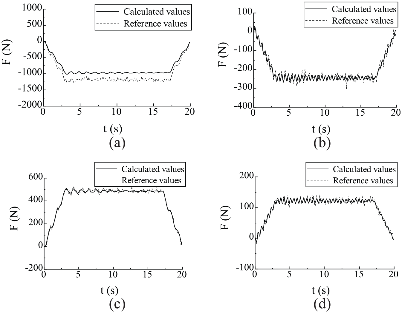
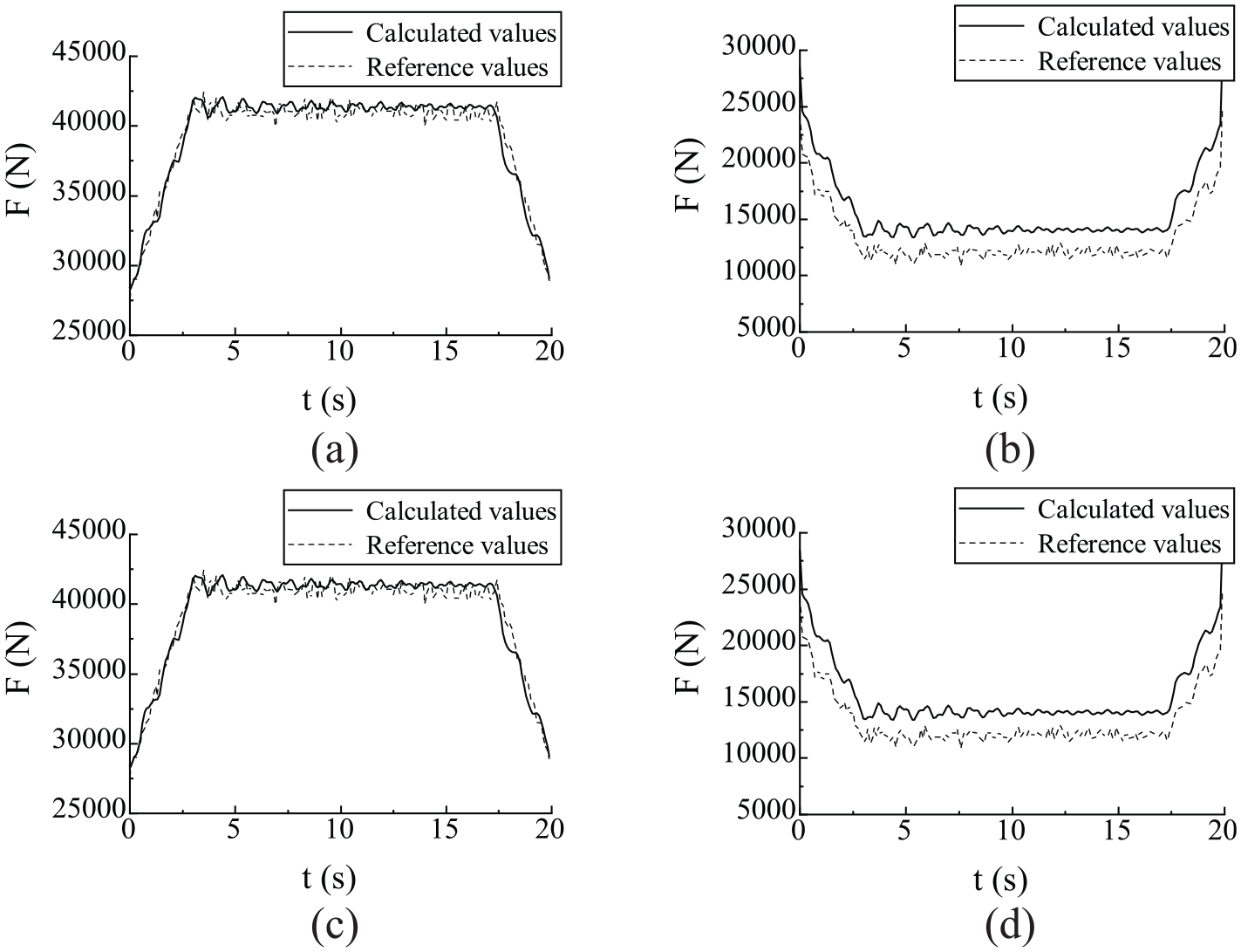
Lateral force of the running wheel tire: (a) left front wheel, (b) right front wheel, (c) left rear wheel, and (d) right rear wheel.
It can be seen from Figure 7 that when the vehicle turns left, the radial force of the left running wheel tires increases gradually from the average value to the maximum value, then runs smoothly at the maximum value, and finally decreases gradually to the average value when turning out, while the change trends of the right wheel tires are the direct opposite. The main reason for this phenomenon is the super-elevation of the track beam and the centrifugal force, which is similar to the radial forces of the left and right tires of the test vehicle on the high speed loop. Figure 8 depicts that the lateral force of the front row running wheel tires is negative while that of the rear row running wheel tires is positive. This can form a shaking moment forcing the bogie to turn and this is consistent with the actual situation. The lateral forces of the left running wheel tires are larger, because the internal wheels have smaller turning radius and larger turning angle when the vehicle turns and this is also consistent with the actual situation. At the same time, as can be seen from Figures 7 and 8, the calculated values of the radial and lateral forces of the running wheel tires obtained by this model have the same trend as the reference values from Zhong’s model. Despite some deviations, the dynamic model of straddle-type monorail vehicle established in this study can still be considered to be reliable.
Finite element model of running wheel tire
Finite element model
In order to analyze the wear of the running wheel tires, an efficient and convenient method is to establish a finite element model based on the corresponding boundary conditions of the dynamic model. The finite element model of the running wheel tire is established in ABAQUS. As shown in Figure 9, CGAX3H and CGAX4H are selected as triangular and quadrilateral elements of rubber materials in the two-dimensional model and the corresponding three-dimensional elements are C3D6H and C3D8H, respectively. The total number of elements is 196,400 and the total number of nodes is 201,050.
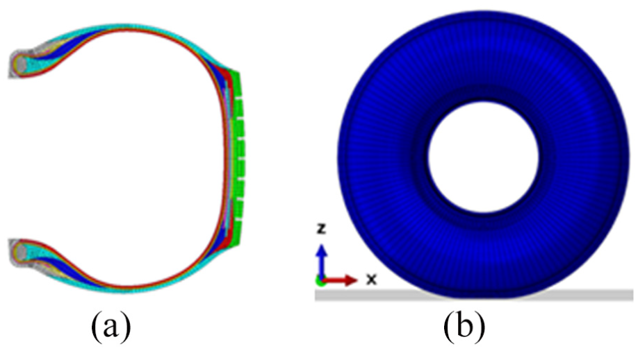
Finite element model of running wheel tire: (a) two-dimensional model and (b) three-dimensional model.
The track beam surface in the model is set as analytic rigid body and the friction coefficient

where
Fitting parameters of friction coefficient.

Finite element model validation
Radial, lateral, and longitudinal stiffness tests of running wheel tires were carried out to verify the finite element model, and the comparisons are shown in Figure 10. The results show that the radial, lateral, and longitudinal stiffness errors of the finite element model are 4.7%, 1.9%, and 2.1%, respectively, which is within the limits of engineering analysis. Thus, the finite element model of the running wheel tire built in this study is reasonable.

Verification of finite element model: (a) radial stiffness, (b) lateral stiffness, and (c) longitudinal stiffness.
Results
Considering the front bogie as an example, the running conditions of four running wheel tires installed on the front bogie are quite different during the turning process, leading to different wear conditions.
Running conditions of running wheel tires
When the straddle-type monorail turns at a minimum radius of 100 m, the corresponding speed is set to 36 km/h. Then, the slip angle, roll angle, and radial force of the running wheel tires can be obtained from the dynamic model of straddle monorail vehicle, and the steady data are shown in Table 3. With these boundary data, contact information of each running wheel tire can be extracted from the finite element model.
Fitting parameters of friction coefficient.

Contact information
Contact pressure
Figure 11 shows the contact pressure of each running wheel tire, it is evident that, the left front or left rear wheel tire subjected to larger radial force is fully in contact with the track beam surface with greater stress at the shoulders than the crown and the roll angle leads to asymmetry in stress distribution. The right front or right rear tire with lower radial force makes lesser contact with the track beam surface even with one side shoulder suspended. The stress at the crown of the right front or right rear tire is larger than the shoulders, and the larger roll angle increases the asymmetry of the contact pressure distribution. Because of the small slip angle of each running wheel tire, there is no significant increase of inhomogeneity in contact pressure; however, the large slip angle may easily lead to an increase in contact pressure at the shoulder and a decrease in contact pressure at the crown.

Contact pressure of each running wheel tire: (a) left front wheel, (b) right front wheel, (c) left rear wheel, and (d) right rear wheel.
Longitudinal shear stress
The longitudinal shear stress of each running wheel tire is shown in Figure 12. Intuitively, the left front or left rear wheel tire has a relative uniform distribution except for a small part of the shoulder which is caused by large slip angle. The right front or right rear wheel tire has an uneven distribution with an opposite stress direction of the crown and shoulder caused by the roll angle.

Longitudinal shear stress of each running wheel tire: (a) left front wheel, (b) right front wheel, (c) left rear wheel, and (d) right rear wheel.
Lateral shear stress
Figure 13 depicts the lateral shear stress of each running wheel tire. The left front or left rear wheel tire has larger lateral shear stress on the grounding front and rear end with opposite direction at each shoulder. Conversely, the right front or right rear has larger later shear stress on the grounding mid-end with opposite direction at each groove. Obviously, the slip angle can change the stress direction on the grounding front and rear end, especially when the tire is subjected to large radial force.

Lateral shear stress of each running wheel tire: (a) left front wheel, (b) right front wheel, (c) left rear wheel, and (d) right rear wheel.
Longitudinal velocity
The longitudinal velocity of each running wheel tire is described as Figure 14. The velocity distributions of the left front and left rear wheel tire are similar with large velocity on the grounding front and rear end. Meanwhile, the velocity of the grounding rear end is larger because of the tension of tread rubber. The velocity at the crown of the right front or right rear wheel tire is larger than that at the shoulders, showing completely different distribution trends compared to the left front or left rear one. And the slip angel and roll angle have no significant effect on the longitudinal velocity distribution of each running wheel tire.

Longitudinal velocity of each running wheel tire: (a) left front wheel, (b) right front wheel, (c) left rear wheel, and (d) right rear wheel.
Lateral velocity
Figure 15 describes the lateral velocity of each running wheel tire. The distributions of each running wheel tire are similar to each other with large velocity at each groove. Due to the extrusion and tension of the tread rubber, the velocity distribution in opposite direction appears near the groove. The roll angel has little effect on the lateral velocity, while the slip angle increases the velocity at the shoulders with different directions on the grounding front and rear end.

Lateral velocity of each running wheel tire: (a) left front wheel, (b) right front wheel, (c) left rear wheel, and (d) right rear wheel.
Wear evaluation index
As the tire wear volume is proportional to the exponential power of friction work in the contact area, 19 friction work can be used to evaluate the wear condition of running wheel tires, as shown in formula (24)

where
In order to characterize the uneven degree of tire wear, the skewness value of friction work as shown in formula (25) is used

where
Wear calculation
The running tire tread is assumed to be divided into three parts, as shown in Figure 16. The overall and local friction work of the tread can be calculated simultaneously so as to study the wear uniformity of each tire. Table 4 shows the friction work and its skewness value of each tread part.

Tread partition diagram.
Friction work and its skewness value of running wheel tires.

Table 4 shows that the tread friction work at the left front and left rear running wheel tires is larger than that of the coaxial right front and right rear ones. And the friction work of left front running wheel tires is greater than the other one because of the large slip and the roll angle during turning. The friction work skewness value of each part of the running wheel tires varies in different degrees. The shoulder wear on both sides of the left front and left rear running wheel tire is more pronounced than that of the wear in crown area, and the shoulder wear on the outer side is more rampant than that on the inner side, resulting in uneven tire wear. The crown wear of the right rear running wheel tire is more severe than that of both shoulders with greater wear of the outside side shoulder, resulting in uneven tire wear. The wear degree of the right front running wheel tire decreases stepwise from the outside shoulder to the inner side shoulder, leading to partial wear. Overall, it can be seen that, all the running wheel tires experience varying degrees of uneven wear phenomenon.
Discussion
The running wheel tires show different degrees of uneven wear under different operating conditions. The main influencing factors are vehicle structure parameters, vehicle operation parameters, and track surface parameters among others. However, the most intuitive influencing factors are the slip angle, roll angle, and radial load of running wheel tires. The running wheel tires show different wear states under the action of each parameter alone or in combination.
Effect of the slip angle on running wheel tire wear
The friction work and its skewness values of the running wheel tire at different slip angles are shown in Figure 17. As depicted by the figure, when the load increases, the wear amount and uneven wear degree of the running wheel tire increases too. Also, when the slip angle increases, the wear amount and its skewness values of the running wheel tire increases. The reason is that when the slip angle of running wheel tire increases, the lateral force increases causing greater shear deformation and slip of the tire tread, resulting in increased wear. And the increased uneven distributions of the tread shear force and slip velocity results in increased uneven wear distribution.

Friction work and skewness of running wheel tires at different slip angles: (a) friction work and (b) friction work skewness.
Effect of the roll angle on running wheel tire wear
The friction work and its skewness values of the running wheel tire at different roll angles are shown in Figure 18. When the load is small, the wear amount increases with the roll angle while the uneven wear degree increases first and then decreases with the roll angle; when the load is large, the wear amount and uneven wear degree of the running wheel tire changes little with the roll angle. The reason for the above is that when the load is small, the roll moment increases with the roll angle which leads to redistribution of physical quantities in the grounding area; including contact pressure, lateral shear stress, longitudinal shear stress, longitudinal slip velocity, and lateral slip velocity, resulting in variation of wear inhomogeneity in the tire grounding area. By comparison of Figures 17 and 18, it can be seen that the slip angle has greater effect on uneven wear than the roll angle.

Friction work and skewness of running wheel tires at different roll angles: (a) friction work and (b) friction work skewness.
Effect of combination on running wheel tire wear
The effect of the side angle or the roll angle alone results in the running wheel tires having different degrees of uneven wear, because there will be a phenomena that causes the contact patch of the wheel tires to experience an increase in the contact length on one side in the case of large side slip angles or large roll angles while the contact length of the other side is reduced, as shown in Figure 19. The contact pressure distribution also obeys the same law, but there is an obvious complementary relationship between the two phenomena; that is, the reasonable matching of the side slip angle and the roll angle can reduce the uneven wear in the running wheel tire.

Contact patch of running wheel tire: (a) large slip angle and (b) large roll angle.
Conclusion
In this study, a 15-DOF vehicle space dynamics model with multi-directional linear elastic tire model was established and the following conclusions are evident:
The study established a straddle-type monorail vehicle dynamic model with a multi-directional elastic tire model, which can effectively output the lateral mechanical parameters of each running wheel tire under different working conditions.
According to the boundary conditions of the straddle monorail vehicle dynamic model output, the finite element model of the running wheel tire was established and the wear condition of each running wheel tire was calculated.
An analysis of the influence of side slip angle and roll angle on the uneven wear of running wheel tires was done and a proposed reasonable matching of side slip angle and roll angle which is beneficial to alleviate the uneven wear of running wheel tires was offered.