
Abstract
Keywords
Introduction
Flapping wing micro-aerial vehicles (FWMAVs) have developed greatly over the last few decades, with relevant research showing significant growth. The design of a FWMAV can be conducted through an examination of natural flyers by mimicking their biological features. Natural flyers are examined for this purpose because they can hover, unlike a fixed-wing MAV. They are also more efficient than a rotary-wing MAV. 1 Using these advantages, the FWMAV is capable of conducting various tasks. Specifically, an insect-mimicking FWMAV operates in a low-Reynolds-number aerodynamic environment. Its flight control is implemented by the unique mechanism of multi-wing operation at a high flapping frequency and with a large flapping amplitude. As a result, FWMAVs may contain complicated mechanisms in order to implement such operations. Moreover, FWMAVs do not have tail wings. To control their fuselage, FWMAVs are required to use simultaneously both sides of flapping wing motions. Currently, many methods for more stable flight are being investigated. George et al. 2 developed a differentially driven flapping wing mechanism. In their examination, the trajectory optimization and load analysis were conducted. Moreover, a number of the previous MAVs were described in detail in their literature.
Some examples of the flapping mechanisms are as follows. One of those is the Nano Hummingbird 3 developed by AeroVironment, Inc. It is one of the most advanced vehicles, able to hover and operate in backward and forward flight. Its driving component includes strings which allows both wings to move simultaneously. Robobee, 4 developed at Harvard University, is the smallest vehicle to use a piezoelectric actuator as its driving component. In addition, a few vehicles, such as the Golden Snitch5,6 by Tamkang University and BionicOpter 7 by Festo, adopt conventional mechanical linkages for flapping wing movements. However, Golden Snitch has slightly longer wing span than it should be in the general definition of MAVs. Also, it is not appropriate for insect-mimicking flight, a tailless flight. Insect-mimicking FWMAVs must generate control forces, i.e. pitching, yawing, and rolling moments, with both wings flapping periodically. This suggests that the aerodynamic forces generated on each side of the wings will become unbalanced momentarily. 8 Based on such physical characteristics, several control mechanisms are available. Nano Hummingbird uses a wing twisting mechanism. 3 This mechanism changes the membrane shape by modifying the trailing edge to generate different lift on each wing. BionicOpter 7 by Festo modifies the direction of the flapping plane of each wing to generate unbalanced aerodynamic force. On the other hand, the robotic hummingbird by Bruxelles University varies the position of its kinematic joints to change the flapping angle and offset of the flapping plane. 8 However, several of the mechanisms mentioned above require a considerable amount of space owing to their large driving or control components. Moreover, modifying the trailing edge requires experimental verification and an aerodynamics database to induce reasonable performance. Significant collaboration with analytical design teams is also required during the design process.
In this paper, a six-bar linkage mechanism is suggested. This mechanism requires a relatively small driving component through two separate kinematical steps relying on its six-bar linkage characteristics. The wing motions for the flight control are simply generated from a small position change of the joints. Additionally, kinematics and structural analyses may provide a more realistic result with regard to the design. With a fundamental analysis using the unsteady blade element theory (UBET), 9 certain design requirements will be established. The design of the flapping mechanism using the present mechanical linkage will then be realized. In order to predict the structural reliability of the present mechanism, a flexible multi-body dynamic analysis using RecurDyn will be performed. In the present mechanism, the wings are connected to the mechanical linkage and are not directly connected to the joint. Thus, it is possible to obtain a sufficient flapping amplitude and adjust the flapping kinematic by varying the joint location. Currently, the actuation mechanism which steers the joints is not yet included. Using the results of the structural analysis, a detailed design of the present control actuation mechanism will be devised. Finally, an experiment on the present mechanism will be conducted to validate the performance, specifically by examining the control forces, flapping frequency, and flapping angle.
Design procedure
In previous studies,3–5,7 a kinematic analysis using multi-body dynamics was not utilized during the design procedure of FWMAVs, although it was capable of providing a significantly precise design result. In this paper, a design procedure which utilizes a multi-body dynamics analysis is introduced, as shown in Figure 1. The design procedure is divided into nine stages, from the design requirement to the design completion. The first stage is the design requirements, including weight and span limits. To uplift the weight, appropriate thrust is needed. The flapping angle and frequency for the thrust are deduced through the second stage, UBET. Third, a conceptual design is conducted to convert the rotation of the motor to the flapping motion. In this paper, the main mechanism is the six-bar linkage mechanism. The next stage is the kinematic analysis. In this stage, the design parameters such as the link lengths and joint positions are determined with regard to the design requirements. The developed idea is then embodied in a three-dimensional CAD shape before the flexible multi-body dynamic analysis is applied. With this three-dimensional CAD design, a flexible multi-body dynamic analysis utilizing the commercial software RecurDyn
10
is conducted to examine the possibility of fabrication via an understanding of the design parameters and execution faults. The sixth stage is the component selection. Commercially available components, such as motor and gears, are purchased, and other components are processed with regard to the result of FMBD. The next stage includes the fabrication and experimental processes. Subsequently, the performance of the conceptual design is evaluated to determine whether to go to the next stage or return to the previous stage. At this stage, the conceptual design is realized by applying the actual materials, and performance of the FWMAV is evaluated using a test bed which takes into account the aerodynamic force, flapping conditions, and design requirements. In the event problems are found, modification and supplementation will be required. Through this procedure, the flapping mechanisms will be optimized for robustness.
Diagram of the present design procedure.
Design requirements
In this section, the preliminary design requirements will be established. First, the wing span was determined to be 150 mm by referring to the definition of a general FWMAV. The gross weight was then assumed to be 20 g by considering off-the-shelf products, such as an electric motor, a servo motor, a joint pin, and others. Finally, appropriate flapping amplitude and actuation frequency which would create sufficient lift were estimated using UBET prediction.
8
UBET refers to an unsteady blade element theory which is based on quasi-steady aerodynamics. In the present UBET analysis, the wing mass and center of gravity were set to 0.1 g and 0.1%, respectively, along the chord length in each case. In addition, three types of wing planforms were considered, i.e. rectangular, elliptic, and insect-like wings. The configuration of the wings is illustrated in Figure 2.
Three-wing planform configurations.
UBET results for flapping amplitude of 150° and frequency of 37 Hz.

Preliminary design requirements for the present FWMAV.

Flapping mechanism
The present driving components consist of a DC motor, gears, and linkages. To generate the flapping motion, the revolution of the motor needs to be transformed into reciprocating angular motion. In the present mechanism, a certain type of six-bar linkage was utilized to provide a combination of two separate types of kinematics. One mechanism close to the input link is the crank-slider mechanism, which consists of a four-bar linkage and which creates back and forth motion. However, the crank-slider mechanism is an asymmetric mechanism, which creates a difference slider speed between the forward and returning stroke, known as a quick return mechanism. To reduce the asymmetric characteristic of the crank-slider mechanism, an alternate step mechanism is required. The second step close to the wing consists of a crossed four-bar link which compensates for the asymmetry of the initial four-bar linkage. Moreover, this second step is capable of amplifying the crank-slider motion, as depicted in Figure 3. This suggests that the final flapping angle can be increased further. Using such a mechanism, it is possible to minimize the dimensions of the driving components and create the desired control capability at the same time. In this section, a parametric design was conducted to satisfy the design requirements acquired in the Design requirements section.
Diagram of the two-step flapping mechanism.
Kinematics of the present flapping mechanism
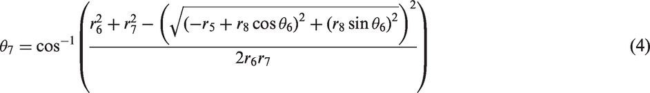
In this section, the formulation for the present six-bar linkage is presented. It was in order to estimate the appropriate length of linkages regarding the required flapping motion, determined in the previous section. Moreover, the formulation was applied to design the control mechanism (see the Control mechanism section). As described at the beginning of this section, the present six-bar linkage uses the following two steps to create the flapping motion. Here, the kinematics of the linkages is analyzed in detail to predict the motion. The first mechanism of the present six-bar linkage can be expressed by taking the geometry and angular motion of the frames into account, as follows.

Here, 

Here, 
By completing these procedures, an accurate prediction of the kinematics of the linkages becomes possible. The flapping stroke amplitude in the present mechanism is obtained by the complicated linkage motion shown in Figure 4. The bending angle of the linkage Kinematic scheme of the present six-bar linkage.
Dimensions of the linkage components.

Control mechanism
Conceptual design of the control mechanism
In this section, a control mechanism using the aforementioned linkage mechanism is presented. In an insect-mimicking FWMAV, the aerodynamic difference between the two wings may introduce unbalanced moment. Therefore, the vehicle is required to have the capability for changing the wings' position. There are two major control mechanisms. One is the trailing edge control (TEC) mechanism which is called as wing twist modulation in Nano Hummingbird.
3
This mechanism changes the angle of attack or camber of the wings by steering the trailing edge. The other is the flapping plane control mechanism. This mechanism is combined with the main flapping mechanism. It changes the flapping amplitude or tilts the flapping plane forward or backward. The present design employed the flapping plane control mechanism by integrating both flapping and control mechanisms. Such compact combination will be beneficial for the design of a small-sized MAV when compared to the trailing edge control mechanism. Figure 5 illustrates the right-hand side of the wing and describes the joint motion along the θ and Kinematic diagram of the moving joint on the right wing.
The two-dimensional multi-body dynamics analysis using RecurDyn, based on rigid body assumption, was conducted to estimate the influence with respect to the position of Joint The trajectory curve of the flapping amplitude. Trajectory of rotation of the flapping center line. Values of the resulting control points. Configuration of the joint positions related with the control points.


Pitching, rolling, and yawing motion
In order to generate the pitching moment, both wings will retain a flapping amplitude, α, of 160°. In addition, the center line of the flapping plane is rotated by the same magnitude, β. The relevant situation is illustrated in Figure 9. In the figure, the aerodynamic center of both wings is segregated from the center of gravity of the vehicle. This causes the nose to move up or down.
Joint position for the pitching motion.
Next, yawing moment can be generated by the unsymmetrical motion of the wings. Both wings retain a flapping amplitude, α, of 160° and each flapping plane is rotated in the reverse direction, as shown in Figure 10. Under this condition, the aerodynamic center of each wing will be rotated in a direction identical to that of the original aerodynamic center location. This will also cause the nose to move up or down, as shown in Figure 10.
Joint position for the yawing motion.
The last moment to be considered is the rolling moment. To create the rolling moment, each wing must have a different flapping stroke amplitude. Furthermore, both sides of the wings have a neutral position on the center line of the flapping plane, Joint position for the rolling motion.
As a result, conceptual design of the control mechanism using the present link mechanism was conducted. Moreover, feasible applications for generating the aerodynamic moments were described. In the next section, three-dimensional implementation and the analysis of the present link mechanism will be presented.
Three-dimensional design
In this section, three-dimensional design of the aforementioned mechanisms was conducted for flexible multi-body dynamics. All the predictions were simulated using the flexible multi-body dynamic analysis program, RecurDyn. In this procedure, the play between the joints and linkages are not considered. First, three-dimensional implementation using CAD was conducted, and prediction regarding the flapping mechanism was conducted. The relevant comparison of the quasi-steady response induced by the control mechanism is then described in the following section. Moreover, stress prediction of the present mechanism was conducted in order to estimate the relevant thickness of each linkage.
Flapping mechanism
Before the flexible multi-body dynamic analysis of the present mechanism is applied, a three-dimensional model was created. Based on the kinematic analysis, the three-dimensional flapping mechanism was created, as shown in Figure 12. It consists of rivets, a DC motor (DiDEL MK07-08), gears, brass bearings, and the fuselage frame (epoxy glass laminate). In its three-dimensional configuration, multiple numbers of yellow circular-sectional shaft pins represent the hinge fixed on the fuselage frame, which withstands the bulk of the load generated by the flapping motion. The motor and gear box are located below the present mechanism. These components are located between the two wings considering the center of gravity of the entire vehicle. The linkages, which are similar to tongs, are capable of holding the wing batten connected to the wing membrane. The material of the present fuselage frame is an epoxy glass laminate, which is light and structurally strong. The flapping amplitude of the present three-dimensional configuration was estimated in the flexible multi-body dynamic analysis. To evaluate the accuracy of the kinematic solution, the analysis was performed while assuming only rigid-body rotational motion. As shown in Figure 13, the results obtained with this mechanism showed an upstroke and down-stroke with symmetric amplitudes at a constant time step. Thus, the stroke motion was relatively well matched by the sinusoidal curve. Moreover, the flapping amplitude was estimated to be sufficient, at approximately 160°.
Three-dimensional CAD drawings of the flapping mechanism. (a) Front view and (b) isometric view. Rotation angle result of the flapping wing mechanism.

Control mechanism
As shown in Figure 14, the control mechanism was designed to generate joint motion by obeying specified requirements in the Control mechanism section. In the present three-dimensional configuration, a simple rotating and pulling mechanism was utilized to simplify the fabrication procedure. To analyze the control mechanism, a multi-body dynamic analysis by RecurDyn was used. In Figure 15(a), the components in blue were devised to control the θ rotation while those in brown are devised to control the Three-dimensional CAD drawings of the control mechanism. Three-dimensional CAD drawings of the control mechanism: (a) θ - Motion, (b) 

First, the joint motion was prescribed to change the flapping stroke amplitude α. Recalling the control points depicted in Figure 8, the joint position was varied. When the joint was located at the control point, Flapping amplitude variation according to the joint motion of the θ and 
In order to generate the yawing motion, the flapping amplitude was held constant but the flapping plane should be rotated. Therefore, the joint was located at the control point, Flapping amplitude variation according to the joint motion of the θ and 
Stress prediction using flexible multi-body dynamic analysis
After the verification of the flapping and control mechanisms was completed, a flexible multi-body dynamic analysis was conducted to predict the stress induced in the linkages. In this analysis, the flapping frequency was set to be 37 Hz, which was the design requirement. From the prediction on the stress in the linkages, the relevant stiffness of each link was determined by adjusting the thickness of the link. The thickness of all the linkages was determined to be the same in the initial design. However, the maximum stress induced in Links 1 and 5 had been predicted to be larger than the yield strength of the constituent material, i.e. epoxy glass laminate. Epoxy glass laminate has a yield strength of 870 MPa. After the thickness of Links 1 and 5 was adjusted, the analysis was re-conducted. The relevant result is illustrated in Figure 18. The maximum von Mises stress was predicted to be 291 MPa, as shown in red in Figure 18. By comparing the maximum predicted stress with the material yield strength, the safety of the proposed mechanism was proved. The margin of safety was 67%. However, in the flexible analysis, only flapping operation in a vacuum was considered. In order to obtain a more realistic prediction, the aerodynamic loads induced by the flapping motion will be predicted and added.
Result contour of Link 1 as predicted by RecurDyn.10 Result contour of Link 5 as predicted by RecurDyn.10

Fabrication and experiment
Fabrication
Figure 20 shows the fabricated prototype. To satisfy the design requirement weight, the fuselage was made of epoxy glass laminate, a relatively lightweight material with high solidity compared to other materials. Here, 1 mm and 2 mm plates of epoxy glass laminate were prepared by a CNC cutting machine for the fuselage components. In all of the connected joints, the brass bearings having a diameter of 0.8 mm were used to maintain the accuracy and minimize the rotational friction. The motor that was selected for use was the MK07-08 by DiDEL. It can generate 0.37 N-mm of torque at 40,000 r/min with no load condition at 4.5 V. A nine-tooth pinion, a 12/36-tooth gear, and a 12/60-tooth gear by DiDEL were used to obtain a 20:1 gear ratio. Using this gear ratio, the motor will provide 7.4 N-mm of torque at 2,400 r/min with no load condition at 3.5 V. This condition was selected considering the predicted flapping frequency of 37 Hz. Consequently, the external dimension of the driving component was 25 × 26 × 30.2 mm and the gross weight was 8.3 g, not including the battery. The flapping wing had a wingspan of 150 mm, and its wing membrane was made of polyethylene with a thickness of 15 microns. To support the wing, a 1 mm carbon rod was used at the leading edge of each wing. The membrane did not adhere to the carbon rod but instead enclosed the rod. Thus, when the FWMAV is in the flapping condition, the wing membrane rotates freely along the leading edge according to the inertia of the wing.
Assembled prototype.
The total span is 150 mm and the weight is 8.3 g. These values are slightly smaller than those of Nano Hummingbird, which are 158 mm and 8.88 g, only including the main motor, flapping mechanism, wings and structure. 3
During the fabrication of the control mechanism, the control joints were fixed at the control locations to implement each different control input, as depicted in Figure 8. Hence, four different types of the prototypes were fabricated in order to implement each control for neutral, positive pitch, roll and yaw.
Experiment
Using the fabricated prototype, the flapping wing trajectory was evaluated. The trajectory was measured by a high-speed camera, the Micro M100 by Phantom. In order to measure the amount of the flapping angle in the wing, each frame was analyzed to find out the peak-to-peak postures. In the test, the input voltage to supply the power was 4 V. It generated a flapping frequency of 23 Hz. The present mechanism was fixed on an extra mount, as shown in Figure 21. The first condition was the neutral condition, as shown in Figure 22(a). The flapping trajectory appeared to be symmetric, and the relevant flapping amplitude α was approximately 160°. Subsequently, by following each joint location, the three cases of flapping trajectories, i.e. pitching, rolling, and yawing motions, were tested. The position of each joint was based on the specifications described in Control mechanism section. The second condition was the pitching motion. The centerline of the both wings was rotated symmetrically by 8°. This motion was in good agreement with the analytical solution, as shown in Figure 22(b). The third condition was the rolling motion. For the rolling motion, from the analytical estimation, one side of the wings was 176° while the other side was 144°. As shown in Figure 22(c), these values were also in good agreement with the experiment results. The final condition was the yawing motion. It also matched the analytical solution well, as shown in Figure 22(d). In all of the conditions, there were differences of approximately ±5° between the analytic solution and the experimental results. There are several possible reasons for such differences. First, in the actual experiment, there was additional aerodynamic force on the wing surface, but it is not considered in the multi-flexible body dynamic analysis. Second, there were manufacturing inaccuracies which were generated by the CNC cutting machine or abrasions created during the fabrication procedures.
Flapping motions captured by the high-speed camera. Fabricated prototype.

A FWMAV must change its wing aerodynamic force in order to control its position or its fuselage attitude. To validate the control capability of the FWMAV here, a test bed was created. A Nano-17 load cell by ATI was used to measure the force and moment components generated by the modification of the wing kinematics. An experimental mount with three-axis degrees of freedom was designed. It can trim the fuselage posture to obtain a more precise result while remaining connected to both the load cell and the flapping mechanism. Figure 23 shows the flapping mechanism mounted on the test bed and load cell. During the measurement, the relevant values were transformed to those referring to the center of gravity of the mechanism by using the module included in DAQ system (DAQ Force and Torque Manual Calculation). The positive Z-axis heads vertical upward of the load cell, and Y-axis lies in the center line of the flapping plane. Figures 24 and 25 show the load components obtained. All the results were smoothed by applying a low-pass filter (cut-off frequency 50 Hz). Figure 24 presents the quasi-steady responses of the 6-DOF forces and moments for 1 s after 5–6 s of operation. Figure 24(a) and (b) shows the results for the neutral state, without any control inputs. The average value of the measured vertical load was 0.141 N. Because the mass of driving component is 8.3 g, 0.081 N is needed to hover and it is expected that the present flapping mechanism is capable of flying. Moreover, the vertical load was 67% higher than the value of other linkage flapping mechanism, which was 0.84 N at 37 Hz of frequency with same span.
9
Because the present mechanism generated more thrust at lower frequency, the efficiency of the complete system is expected to be high. However, compared with the string mechanism of Nano Hummingbird, the present linkage mechanism needs more improvement. As Nano Hummingbird can lift its total mass 19 g, the thrust is at least 0.186 N which is 32% higher than the present value. Figure 24(c) and (d) shows the response for the pitching input in the (+) direction, which is (+Y) rotation. The measured average pitching moment was 0.282 N-mm. Next, the rolling moment in the + direction (+X rotation) was measured. The generated rolling moment was 0.75 N-mm, as shown in Figure 24(e) to (f). This value corresponds to the average rolling moment. The last quantity measured is the yawing moment. During the yawing motion, both wing planes were rotated in the same direction, either clockwise or anticlockwise. By this motion, the yawing moment was generated. The average value of the yawing moment was 0.29 N-mm. These mean values were compared in Figure 25 to evaluate the coupling between the control inputs. In Figure 25(a), the control inputs did not change the lift significantly, while the x-direction force was varied a little. In Figure 25(b), at the neutral condition, small amounts in three moment components were induced due to inaccurate fabrication or wrong estimation of the gravity center. And for each control input, certain moment component became increased, almost twice larger than the remaining moments. Thus, it is concluded that coupling between control inputs is negligible. In this experiment, the amounts of control force and moment generated by the present flapping mechanism were measured and examined. As a result, it was confirmed that the control forces and moments would be generated independently to adjust the fuselage attitude in the proposed vehicle.
Fabricated test bed and load cell. Quasi-steady responses for 1 s for each control input: (a) Force response for the neutral condition, (b) Moment response for the neutral condition, (c) Force response for the pitch control, (d) Moment response for the pitch condition, (e) Force response for the roll control, (f) Moment response for the roll condition, (g) Force response for the yaw control and (h) Moment response for the yaw condition. Mean components for each control input. (a) Mean force component for each control input. (b) Mean moment component for each control input.


To confirm the generated lift of the flapping mechanism, a vertical takeoff experiment was conducted, as shown in Figure 26. The input voltage of the supplied power was 4 V, generating a flapping frequency of 24 Hz. In this experiment, the flapping mechanism consists of only the driving components, not including therefore the battery or control system. This test focused on only the vertical thrust. Thus, the flapping fuselage was guided with iron string, which was connected to the experimental mount. In the flapping mechanism, a brass bearing was used to minimize the friction between the string and the flapping fuselage frame. The diameter of the strong was 1 mm and its length was 100 mm. Each end was fixed strongly to the experimental frame. This constrained the vertical direction motion of the present flapping mechanism. The direction of the stroke plane is identical to the horizontal plane, as shown in Figure 26. The result showed that the flapping mechanism could make sufficient vertical thrust. When the input voltage is supplied, the flapping frame will move upward. This suggests that the flapping mechanism can generate enough lift for takeoff.
Guided vertical takeoff experiment. (a) t=0 s, (b) t≈2 s, (c) t≈3.5 s, and (d) t≈5 s.
Conclusion
In this paper, a new FWMAV was designed from the conceptual design stage. First, several design requirements were established using UBET. In keeping with these requirements, a detailed design of the flapping mechanism was done. For the flapping mechanism, a six-bar linkage was used, and it was expected to have a sufficient flapping stroke amplitude of approximately 160°. The total span and the weight were slightly smaller than those of Nano Hummingbird, which is expected to be advantages for FWMAV. The control mechanism was then considered to generate the flight control moment for pitching, yawing, and rolling motions. This control motion was implemented via a combination of motions by joints. The present control mechanism using the joint motion induces the motion difference between the two wings. As a result, the vehicle is capable of changing two wings' aerodynamic forces. The present concept is an integrated form of both flapping and control mechanism, which will be beneficial for the design of a small-sized tailless MAV. However, the present mechanism becomes structurally more complicated to fabricate than the other existing link mechanisms. A three-dimensional model was then created to consider the actual components and materials. To confirm the performance of the proposed design, a multi-body dynamic analysis was conducted using RecurDyn. In the analysis, the flapping amplitude was predicted to be approximately 160°. The control motion for changing the wing kinematics was also predicted by considering the joint motion along with variations of this motion. Then, the three-dimensional CAD drawings were created. Finally, the performance of the present design was evaluated in an experiment. The wing trajectory was captured by a high-speed camera. This procedure made it possible to estimate the performance of the mechanism and the fabrication error. The results were in good agreement with kinematic analysis to within ± 5°. An experiment using a load cell was conducted to evaluate whether or not the generated amounts of moment could allow takeoff or proper changes of the vehicle attitude. The measured lift was much greater than that of the other linkage mechanisms, but much smaller than that of the string mechanism. It was found that the friction between the links needs to be reduced for improved efficiency. The measured pitching, rolling and yawing moments demonstrated the possibility of the control capability of the designed mechanism. However, fabrication based on this concept was undesirable, since internal and external loads were not considered. Thus, flexible multi-body dynamic analysis will be conducted by considering aerodynamic loads induced by the wing motion. In addition, the actuation mechanism controlling the joints will be designed. A comparison between the joint steering mechanism and trailing edge control mechanism which is also in progress, will deduce the proper control mechanism for the present six-bar linkage FWMAV. As a result, a detailed design of the FWMAV will be improved. Moreover, the free flight test using the present mechanism will be conducted. Especially, vertical takeoff will be examined in order to figure out the potential problem regarding the balance of the vehicle by using the presently equipped device, i.e. high-speed camera.