
Abstract
Introduction
Modern Uninhabited Aerial Vehicles (UAVs) have been utilized for a myriad of applications in a broad scope of use-cases from recreational to military. Whether flying around a bridge or industrial structure to inspect for wear, hovering over an agricultural field to measure moisture and yield, or swiftly delivering packages to your front door the utility of UAVs is appreciated in a multitude of sectors. These aircraft have been designed at all sizes from the behemoth 16-ton Global Hawk to the diminutive 30 mg Robobee.1,2 The term Micro Air Vehicle (MAV) was coined in 1997 when the Defence Advanced Research Projects Agency (DARPA) defined such a vehicle as a UAV weighing 100 grams or less (including a 20-gram payload), having endurance of 1 hour, with a range of 10 km, no dimension over 6 in, and a maximum speed between 10 and 20 m/s. 3 MAVs in a military context were envisioned to be cheap, compact, man-portable devices that could be rapidly deployed in a variety of situations requiring remote observation or sensing. Because of their size, these vehicles can operate in constrained spaces like buildings, caves, or dense flora that normally prohibit UAV flight. Soldiers on the ground could leverage all the advantages of remote sensing without hauling pounds of extra gear. Small aircraft also have inherently reduced signatures and therefore, are less likely to be detected, which makes them suitable for clandestine operations. One example of a military MAV is the Black Hornet helicopter from FLIR, shown in Figure 1.

A soldier deploying a FLIR Black Hornet MAV.
The advantages of an aerial platform at this scale are attractive to not only the military, but also to the broader commercial and personal user. Small platforms can maneuver in confined spaces like industrial complexes or other infrastructure to perform inspections or take photographs while reducing the risk of damage from collisions. Moreover, the reduced signature is beneficial to many users who might not wish to disturb their subjects with the normally irritating noise of larger UAVs (e.g., wildlife or wedding photographers).
However, even though many MAVs have been designed, their adoption and use in military and commercial spaces remains limited despite great improvements in electronics, materials, and battery technology. This fact is related predominantly to two fundamental challenges that arise when designing MAVs, which are (1) the poor performance of airfoils at low Reynolds numbers (
Challenge - low relative lift at low Reynolds numbers
As

Challenge - high susceptibility to disturbance at small scales
Disturbance tolerance is detrimentally impacted by the way in which physical properties change with size. An intuitive understanding of this can be obtained from simplified length-based scaling relations. Table 1 shows several physical properties and how each changes with a characteristic length,
Relationships governing scaling based on characteristic length

The novel cyclocopter
In the endeavor to address both of these shortcomings, researchers and engineers have designed all types of MAVs; however, they can generally be divided into three archetypes: fixed-wing, rotary-wing, and flapping-wing. Each method of lift production lends itself to different mission profiles because of its innate strengths and weaknesses. Fixed-wing UAVs tend to have higher endurance while rotary-wing vehicles are more maneuverable. Flapping-wing UAVs are still predominantly experimental due to the mechanical complexity associated with reciprocating wings and the incomplete understanding of flapping flight. 20
But the currently limited application of MAV platforms alludes to the need for a non-traditional solution. One possibility is the cycloidal rotor (or cyclorotor), a novel rotary-wing lift-generation device with several unique properties that could fundamentally address the challenges of flight at MAV scales. Unlike a traditional rotor, the cyclorotor utilizes a horizontal axis of rotation with the blade span parallel to the axis. Lift is generated by pitching the blades as they rotate about the azimuth with a cyclic frequency of once per revolution. Figure 3 illustrates the lift and drag on the blades at various points in the rotation along with the total thrust force. Net thrust is upwards because there is a positive geometric angle of attack in the top and bottom halves of the trajectory. Magnitude and direction of the resultant thrust can be changed by altering the amplitude and phase of the cyclic blade pitch kinematics, respectively. Pitch phase is the angle between the azimuth (

Blade kinematics and force on a cyclorotor.
Past cyclorotor studies
The cyclorotor concept was envisioned over a century ago, but has only seen limited application since, the most prominent example being the Voith-Schneider Propeller used on aquatic vessels, shown in Figure 4. With the advent of modern materials and electronics, flight-capable cyclorotor-based vehicles, or cyclocopters, have been built at a range of sizes from 30 grams up to over 100 kilograms.22–24 These were made possible by rigorous scientific study into the fundamental operation and aerodynamics of cyclorotors. Prior research includes extensive analysis conducted by the authors25–31,22 including detailed performance measurements and flow-field analysis via Particle Image Velocimetry (PIV) for the purpose of optimizing the force production and aerodynamic efficiency of an MAV-scale cyclorotor.

Two Voith-Schneider propellers installed on a ship.
In order to predict the hover performance of a cyclorotor, an aeroelastic model was also developed and validated for operating Reynolds numbers between 80,000 and 200,000.32,33 Further, this model was incorporated into a coupled trim model to predict and analyze achievable trim states for twin-cyclocopter designs. 34 Note that all the previous cyclorotor performance models assumed 2D aerodynamics because of the high aspect ratio of the blades, were developed for moderate to high Reynolds numbers, and the aeroelastic model approximated the blade structure as a slender beam. However, the current quad-cyclocopter design utilizes low aspect ratio insect-like wings where the aerodynamics are highly three dimensional, 22 operates at a Re = 11,000, and uses a plate-like blade structure. Therefore, the previous analytical models could not be directly used for developing the current aircraft; however, an in-house aerodynamic model was used to guide the preliminary design.
The only other documented quad-cyclocopter to achieve forward flight weighed 1 kilogram and had a significantly different cyclorotor design. 35 That larger vehicle, developed at the University of Maryland, was capable of flying, rolling on the ground like a car by using its cyclorotors as wheels, and traversing water on floats. It incorporated cyclorotors with blades supported on both ends that had a rectangular planform and thick, symmetrical airfoils. More details about the differences between that cyclorotor design and the one presented in this paper can be found in Refs. 22 and 36.
The subject of this paper is part of a larger body of research by the authors into MAV-scale cyclocopters and is one of several flight-capable cyclocopters developed by the authors, pictured in Figure 5. The 30-gram vehicle is the smallest cyclocopter ever developed with two co-rotating cyclorotors measuring 1 inch in radius. 37 Flowfield measurements were taken using PIV on the micro-cyclorotor, which showed that the flow was highly 3-dimensional and vortical, 22 unlike many of the previous designs that had largely 2-dimensional flow because of the high aspect ratio rectangular planform blades. 28 More information on the aerodynamic conditions of the micro-cyclorotor can be found in Ref. 22. The 33-gram coaxial-nose twin-cyclocopter is the only documented twin-cyclocopter to use a coaxial nose rotor and was used to experimentally extract a linear model of its bare airframe dynamics through system identification techniques. Swapping the single nose rotor for a coaxial rotor system greatly increased handling. Additionally, the linear model and flight-testing showed that the vehicle was passively stable in roll, making it the only cyclocopter to exhibit this property. 38 The primary benefit of the coaxial nose rotor was balancing the reaction torque from the nose rotor about the vertical axis such that the vehicle only experienced a net angular momentum about the lateral axis from the co-rotating cyclorotors. Gyroscopic coupling between vehicle states was still present, but to a lesser degree. Motion in one state would not affect the other states as much. The marked improvement in flight quality from balancing one of the two directions of angular momenta present on the body was one impetus behind the development of the quad-cyclocopter, where there is zero net angular momentum on the vehicle and hence no gyroscopic couplings. Additional motivation was the improved actuation potential of a quad-cyclocopter, as will be explained later in the paper. The remainder of this paper discusses the design, development, and flight-testing of a micro quad-cyclocopter to prove viability at MAV-scales and to experimentally investigate its flight dynamics and controls capabilities.

Quad-cyclocopter configuration
There are two key characteristics that distinguish the quad-cyclocopter from the previously designed twin-cyclocopters. One of which is the presence of additional control parameters giving the quad-cyclocopter greater actuation potential. Each cyclorotor has two actuators: a motor to command RPM and a servo to command the phase of blade pitching (i.e., thrust direction). Commanding pitch phase is similar to commanding thrust direction, but with an RPM-dependent offset caused by rotational effects. The coaxial-nose twin-cyclocopter had two cyclorotors and two nose rotors for a total of 6 control parameters (4 motors and 2 servos). On the quad, four cyclorotors equate to 8 actuators (4 motors and 4 servos). Over-actuation enables the twin and quad to perform longitudinal translation at a constant pitch attitude, not possible for traditional rotorcraft. The additional controls of the quad permit it several more unique maneuvers for heightened mobility, namely point hover within a range of pitch attitudes and lateral translation at a constant body attitude. The specifics of these maneuvers will be discussed in a later section.
The second characteristic is the balancing of all angular momenta on the body. Nose rotors on the twin-cyclocopter serve the dual purpose of countering the cyclorotor reaction moment and providing extra lift; however, counter-rotating cyclorotors could perform the same functions instead. There are many cyclocopter configurations that can lead to zero total angular momentum — using multiple cyclorotors of the same size rotating at the same speed or several sizes of cyclorotors at different speeds. From the possible options, only those that used one size of cyclorotor were considered for this study to avoid the need of developing two different sizes of cyclorotors for a single vehicle.
Available quad-cyclorotor configurations were then limited to two options, either a “+” or an “H”. In the “+” configuration (Figure 6) the opposing cyclorotors are contra-rotating. While in hover or low-speed flight this creates a highly mobile vehicle capable of longitudinal and lateral translation with no change in body attitude. However, with respect to oncoming air flow in forward flight, one cyclorotor is forward-spinning while the other is back-spinning, which causes an increasing thrust differential as advance ratio increases due to the virtual camber effect, which has a similar impact as that of advancing and retreating sides of a conventional helicopter rotor. For more information on the virtual camber effect see Ref. 39. The “H” configuration (Figure 7) sacrifices lateral translation ability for improved forward flight speed and performance because there is no lift differential in forward flight. Opposite cyclorotors now spin in the same direction while the front and back pairs counter-rotate. Rotation is such that the outermost blades are descending and the innermost blades are ascending, which is necessary to enhance the pitch control moment.

Quad-cyclocopter utilizing a “+” cyclorotor arrangement. 40

Quad-cyclocopter utilizing an “H” cyclorotor arrangement. 41
To explain why, consider a nose-up pitch maneuver. A pitch-up moment is generated by increasing the RPM of the front cyclorotors, while that of the rear cyclorotors is decreased. Not only does this change the cyclorotor thrust, but it also imparts a torque on the body due to the change in power required to spin the motor. When the cyclorotors are spun towards the center (Figure 8), the torque change (

Inward rotation of cyclorotors with opposing reaction torque and lift differential pitching moment.

Outward rotation of cyclorotors with cooperating reaction torque and lift differential pitching moment.
Ultimately, the counter-rotating “H” configuration was chosen for the present design because of the increased forward flight performance over the “+” arrangement. This configuration also enabled the ability to freely change pitch attitudes, which is not allowed by the co-rotating twin-cyclorotor design. Development began with a survey of available commercial off-the-shelf (COTS) parts followed by an estimation of the total vehicle weight from the selected hardware. By mirroring the previously designed twin-cyclocopter about its lateral mid-line a quad-cyclocopter could be created. Estimated weight of a quad-cyclocopter produced in this manner was calculated to be 55 grams; however, each cyclorotor was only designed to produce 10 grams. A detailed discussion of the optimized cyclorotor utilized on the twin-cyclocopter can be found in Refs. 22,37. For the quad-cyclocopter, new cyclorotors capable of more thrust had to be developed.
Cyclorotor development
Rather than completely redo the design process carried out to optimize the cyclorotor for the twin-cyclocopter,
22
it was assumed that the increase in Reynolds number would be small enough to not alter the design parameters that had been experimentally optimized. As a result, a scaling approach was taken to geometrically scale the cyclorotor from the previously optimized twin-cyclocopter by assuming a
Cyclorotor and pitching mechanism design
The cyclorotors used a cantilevered blade design that leveraged the inherent increase in structural stiffness-to-mass ratio associated with reducing scale to produce a lightweight, yet stiff cyclorotor. A single end-plate made of two

A passive 4-bar linkage mechanism was used to cyclically pitch the blades. Figure 11 shows a schematic of the mechanism and the four lengths that comprise it. On the vehicle, this system was sandwiched between the two frames for protection and reduction of parasitic drag.

4-bar linkage system implemented on the micro-cyclorotor. 45
Lengths used in the 4-bar pitching mechanism.

Figure 12 shows an exploded view of the cyclorotor and pitching mechanism. Pitch links (B) were manufactured from a single strand of unidirectional carbon fiber prepreg laid into a TeflonTM mold with a silicone mat to compress the fibers into the mold. Using a silicone mat instead of a male half of the mold evenly distributed the clamping force and relieved pressure points that could damage the carbon fibers. This mold-layup process is similar to the method used to manufacture the blades described in the next section. The center-to-center distance in the mold between the loops at the ends of the pitch links was made 0.018 inches shorter than the designed length to account for some post-removal stretch of the linkage. Pitch links made in this fashion weighed 0.01 grams and were strong in the direction of loading because of the alignment of the fibers with the load. Loops at either end of the pitch links fit around bushings on the other components for ease of movement. At the center of the cyclorotor a Delrin® peg glued into the pitch offset (C) served as the bushing for all four pitch links. On the blades, a PEEK bushing (G) was fixed onto a 0.7 mm carbon fiber rod at the trailing edge.

Exploded view of the cyclorotor, pitching mechanism, and blades with parts labeled. 22
Blade design and manufacturing
The hallmark of the micro-cyclorotor design for the twin-cyclcopter was its lightweight, elliptical-planform, flat-plate-airfoil blades and a more detailed description of their development can be found in Ref. 22. A brief overview is provided here. The bio-inspired elliptical planform was chosen to improve aerodynamic efficiency while mimicking flying creatures that operate at similar Reynolds numbers. A flat-plate airfoil was chosen because it performs better than conventional airfoils at these low Reynolds numbers.
15
Keeping blade weight low was imperative to creating a lightweight cyclorotor because every unit of blade weight generated 590 times that amount of centrifugal force (acceleration of 590 g), causing greater deflection, in turn driving up cyclorotor structural weight required to resist bending. Each blade weighed approximately 0.12 grams which corresponded to 71 grams of centrifugal force, well above the 16 grams of aerodynamic loading. In order to manufacture lightweight blades with consistent properties and quality, a TeflonTM mold layup similar to that used for the pitch links was employed (shown in Figure 13). First, an extra-long piece of unidirectional carbon fiber prepreg was placed into a channel in the TeflonTM mold that formed the mid chord such that some length protruded beyond the top of the groove for the planform shape. Then the planform shape of the blades was formed by laying a continuous length of unidirectional prepreg in the this groove to make two passes around the edge. Between the first and second passes, a length of 0.7 mm unidirectional carbon fiber rod was placed at the mid chord and trailing edge to act as the pitching axis and pitch link attachment point, respectively, shown in Figure 13. Placing the blade pitching axis at the mid chord (i.e., coincident with the blade center of gravity) through structural design reduced blade elastic twist from centrifugal forces. Next, the extra length of prepreg protruding beyond the top of the planform groove at the mid chord was folded back over onto the carbon fiber rod sandwiching the two outer passes and rod. Doing so increased contact surface area between the layers and improved bond strength. Finally, the Teflon mold and silicone mat were clamped between sheets of aluminum and placed in an oven to cure for 135 minutes at

Mold layup assembled in C-clamp prior to curing (offset to show layers).
Vehicle design
With the cyclorotors designed, they could then be incorporated into an “H” configuration quad-cyclocopter using a combination of custom and commercial off-the-shelf (COTS) parts. The 58-gram quad-cyclocopter shown in Figure 5 was the first iteration of the vehicle with power supplied at 3.85 V by two 260 mAH LiHV (Lithium polymer High-Voltage) batteries wired in parallel (1 cell in series, or 1S) on the underside of the airframe. Although this vehicle could lift-off and hover, flight time was severely restricted because the voltage drop under load reduced the motor RPM. To compensate for this quick voltage drop, the cyclorotor power system was converted to 7.7 V 2S (2 cells in series). The under-slung batteries were rewired in series and the electronic speed controllers (ESCs) were upgraded to handle the additional voltage. A second 260 mAH LiHV battery was added on top of the airframe to supply 1s power to the flight controller and servos. These changes added weight, bringing the total to 70 grams, but allowed the motors to spin the cyclorotors at a higher RPM in order to produce more than the initial design of 68 grams total thrust. Maximum thrust with the new electronics was not measured because the vibrations on the constrained test stand at higher RPMs threatened the structural integrity of the vehicle. Regardless, the additional voltage and thrust allowed the quad-cyclocopter to fly for approximately 3 minutes while performing a mix of hover and translational flight.
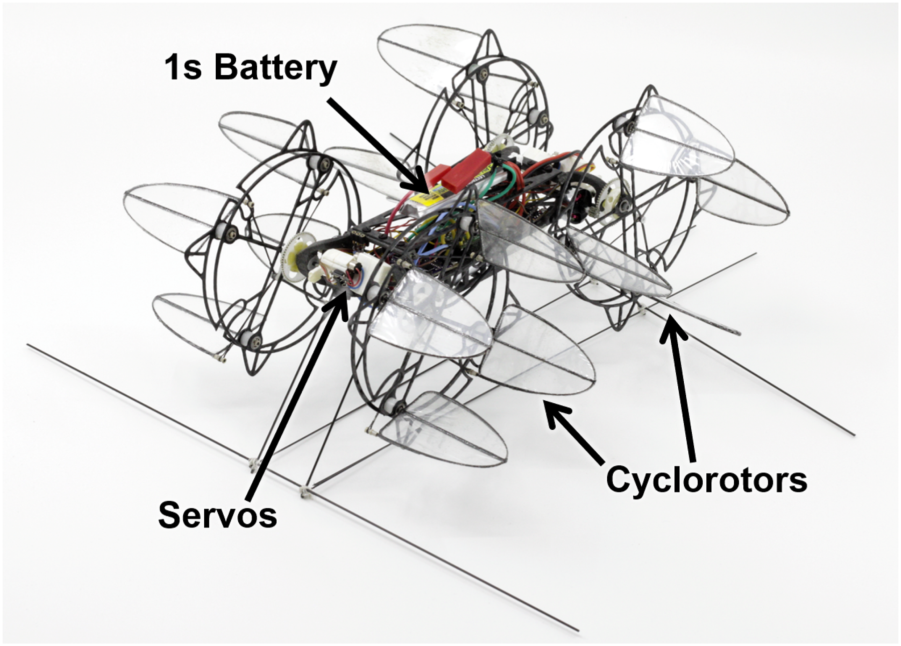
Selective laser sintering (SLS) was used to manufacture the airframe from glass-filled nylon with carbon fiber reinforcement. It was designed to hold all of the components rigidly in a compact arrangement, shown in Figure 14 with the top structure removed for clarity. The stationary main shaft of the cyclorotors is directly aligned with the rotational output of the servos and the cyclorotor is driven around it by a Hobbyking AP-03 7000 kV motor via a 5.45:1 single-stage gear reduction. The DYS XSD7A electronic speed controllers (ESCs) are glued directly to the airframe and the flight controller is soft-mounted at the CG using foam tape. The servos used were Hobbyking HK-5320 digital servos that were lightened to 1.25 grams each from their factory weight of 1.7 g by removing excess casing, filing down the remaining casing, and cutting off excess wiring. Figure 15 shows the final 70-gram configuration of the vehicle which measures

Top view of the quad-cyclocopter with components labeled showing arrangement on the airframe.
70-gram quad-cyclocopter.
Sub-system weight breakdown of 70-gram quad-cyclocopter.

Vehicle telemetry
The flight controller was a custom-built, embedded processor-sensor board called ELKA-R that was developed at the University of Maryland to facilitate the research of micro air vehicles 46 . It can be seen next to a US quarter in Figure 16 and also in Figure 5 mounted on the cyclocopter at its center of gravity. Total weight of the board was 1.7 grams and it was powered by a single 1-cell 3.85-volt 260 mAh LiHV battery. The flight controller housed a STM32 microprocessor with a 32-bit ARM Cortex F4 core for onboard computational tasks. The MPU-9150 inertial measurement unit (IMU) integrated on the board includes tri-axial gyroscopes, tri-axial accelerometers, and magnetometers. Wireless communications were serviced by an on-board nRF24L01 chip, a low-power 2.4 GHz RF transceiver. The flight controller had a sensor update rate of 500 Hz. Communication with the base station occurred at 50 Hz, which was utilized for streaming vehicle attitude, actuator controls data, and receiving pilot commands 47 . The flight controller was capable of sensing vehicle attitude angles and angular rates and sending corrective signals to the servos for stabilization by varying the pulse-width input to the motors and servos.

Custom-built 1.7-gram kinematic autopilot with U.S. quarter for size comparison.
To communicate wirelessly with the onboard controller, the operator used a LabVIEW interface, which included a wireless 2.4 GHz data link with nRF24L01 transceiver. The base station LabVIEW program allowed the operator to control the vehicle, modify feedback gains, change the sensitivity of pilot inputs, and record attitude data transmitted by the onboard processor. The LabVIEW program received pilot inputs through the use of a DX6i Spectrum transmitter which was hardwired to the base station. The program then communicated with the microcontroller through a wireless radio link and used this connection to send the control inputs and receive the vehicle attitude angle and angular-rate data. The data processing and inner-loop feedback control calculations were performed onboard by the microprocessor.
The on-board gyros measured the pitch (

PPID feedback loop architecture for attitude stabilization and control.
Attitude control
Thrust magnitude was modulated by changing motor RPMs while thrust direction could be varied by rotating the pitch offset links using the servos. Both of which could be commanded independently for each of the four cyclorotors, for a total of eight control parameters. Through combinations of magnitude and phase control, the aircraft could be commanded to roll, pitch, and yaw along with several other unique maneuvers afforded to it by the over-actuated nature. A roll moment was generated by increasing motor RPMs on one side and reducing them on the other to create a thrust differential (Figure 18). Similarly, a differential between fore and aft motor RPMs generated a pitching moment because of the change in thrust and torque (Figure 19). Yaw was controlled by tilting the thrust vectoring servos forward on one side and backward on the other (Figure 20).

Differential RPM generating a positive rolling moment.

Differential RPM and torque being used to create a positive pitching moment.

Differential thrust vectoring being used to generate a positive yawing moment.
Angling all thrust vectors in the same direction produced a pure longitudinal translation with no change in pitch attitude (Figure 21), a capability shared between the twin- and quad-cyclocopters. Specific to the quad-cyclocopter was the ability to perform a point hover within a range of different pitch attitudes. Figure 22 shows how the thrust vectors were skewed simultaneously with a change in pitch to achieve a hovering trim at a non-zero body attitude only limited by the servos’ range of motion. A trim setting was included in the controller that allowed the pilot to set a desired pitch attitude in hover.

Simultaneous thrust vectoring being used to generate a longitudinal force.

Flight test demonstrating hover in a non-zero body attitude achieved via thrust vectoring.
Another possible maneuver not explored in this work is a pure lateral translation, which would have required a modification of the quad-cyclocopter design. If the front co-rotating cyclorotors are swept in one direction and the rear cyclorotors are swept in the opposite direction the servos could be used to produce a pure lateral force on the body by pointing the thrust vectors towards each other on one side of the body and away on the other side. Figure 23 shows an illustration of such an arrangement (

Top-down view of lateral force production by cyclorotors with
Flight testing
Making the quad-cyclocopter flight-ready was a process comprised of four steps (1) trim the servo angles or positions (2) trim the motor speeds (3) tune the rate-based inner PID loop, and (4) tune the outer proportional gains on attitude angles. Trimming the servo angles was done by using a single-axis yaw stand to adjust all the thrust vectors until they were perfectly vertical (Figure 24). Each cyclorotor was spun up individually to a set RPM and then servo position was altered until no motion about the yaw axis was observed. Afterwards, hopping flights were performed without feedback to adjust motor RPMs until roll and pitch biases caused by minor differences in the hardware were removed. Initial flights exhibited moderate stability in yaw; therefore, yaw damping had to be improved via increasing the derivative feedback gains. Once vertical ascension was confirmed, controller gains could be added successively to the inner rate-based PID loop. Properly tuned, the vehicle could be flown using only feedback on angular rates, but with large amounts of drift and high pilot workload. The outer loop proportional gains on roll and pitch attitude greatly reduced both. Time required to trim and tune the controller in order to achieve stable hover for the quad-cyclocopter was comparatively lower relative to the twin-cyclocopters because of the reduced complexity; no consideration had to be given to the gyroscopic couplings, controls mixing, or feedforward gains associated with twin-cyclocopter flight caused by the nose rotor. 38 Flight tests were performed to analyze the vehicle’s response in roll, pitch, yaw, and heave. For all except pitch, behavior similar to that of a typical quadcopter was observed, which is to be expected considering the similarity in force distribution and control strategies employed. Novel behavior was observed in pitch and unique maneuvers in the longitudinal mode were performed that are only possible because of the cyclorotor’s thrust vectoring capability.

Micro quad-cyclocopter mounted on a single degree of freedom yaw stand.
Longitudinal mode
The transmitter pitch stick was configured to command longitudinal motion using either pitch attitude or by thrust vectoring using all of the pitch phase control servos with a switch to toggle between the two modes that could be flipped mid-flight. Figure 25 shows the vehicle in forward flight with a commanded thrust vector phase angle (

Thrust vectoring being used to translate with a level attitude (motion is left to right).

Pitch attitude utilized for forward flight (motion is right to left).
Flight data from a characteristic set of longitudinal maneuvers emphasizes the differences between thrust vectoring and pitching motion. Figure 27 shows body frame longitudinal velocity,

Flight data of longitudinal velocity,

Flight data of pitch attitude angle,

Flight data showing the commanded thrust vector phase angle during operation under two different flight modes.
During thrust vectoring flight, maximum thrust vector phase angle,
By combining a pitch command with an equivalent converse thrust phase command the quad-cyclocopter can change its pitch attitude while remaining in a point hover. Figure 30 shows the data from such a maneuver collected in flight at two different frequencies of manually-controlled inputs demonstrating near-zero

Flight test data showing pitch attitude modulation in stationary hover.
These results reveal a critical aspect of the quad-cyclocopter MAV, that equivalent forward flight performance can be achieved using either thrust vectoring or pitching. The independent nature of these two control methods allows them to be used separately or in conjunction based on the intended purpose. For instance, fixed wings could be added to enhance performance or extend range while pitch attitude is augmented to adjust the wing’s angle of attack separately from thrust direction. Furthermore, a payload attached to the body could be pointed by pitching the vehicle because any attitude about the lateral axis is achievable, only being limited by the actuation range of the servos (e.g.,
However, in order to fully harness the capabilities of the quad-cyclocopter there are several considerations that need to taken into account. Firstly, in high-speed forward flight or at high pitch attitude the effects of drag and cyclorotor interaction need to be considered. High pitch angles will create more drag on the body; however, high-speed flight at level attitude might cause adverse interactions between the front and rear cyclorotors. Offsetting these effects to reach maximum speed could involve finding an optimal pitch attitude that is dependent on forward velocity to minimize the total impact of both. Design changes could also mitigate the issue entirely by laterally or vertically staggering the cyclorotors. Secondly, thrust vectoring and pitch attitude control methods have different response times. Changing pitch attitude requires overcoming vehicle inertia, whereas thrust vectoring depends on the actuator speed. The disparity between the two approaches will grow with scale as inertia slows down the vehicle dynamics, reducing the response time. At MAV-scales with relatively small inertia the difference between the two control methods is small; however, on larger vehicles the faster response time of thrust vectoring might impart greater maneuverability to a cyclocopter above that of traditional vertical flight aircraft designs.
Summary and conclusions
Cyclorotors are novel lift generation devices that are still in the nascent stages of being understood and utilized in flying vehicles. The first flight capable cyclocopter was developed relatively recently in an effort to study the potential advantages cyclocopter flight might possess related to maneuverability, efficiency, and gust tolerance.44,45 The research in this paper examines how cyclorotors applied at MAV-scales might compensate for some of the inherent detriments associated with small aircraft, specifically low Reynolds number flight and poor gust tolerance. Presented herein was the design, development, and flight-testing of a 70-gram quad-cyclocopter for the purpose of exploring its unique capabilities. The vehicle used 4 cyclorotors with cantilevered, elliptical planform, flat-plate airfoil blades in an “H” arrangement and was the smallest quad-cyclocopter ever made. A systematic flight-testing procedure was employed to safely trim the 8 independent control parameters to achieve free flight. Subsequently, data was collected on longitudinal maneuvers to compare different modes of translation control. To date, it is one of only two quad-cyclocopters that have achieved forward flight, the other being more than an order of magnitude heavier and a substantially different design. Several important insights were gained through this work:
Eliminating all angular momenta allowed for the simplification of flight control laws by removing the need to compensate for gyroscopic couplings or asymmetrical controls possessed by twin-cyclocopter configurations. Improved handling and flight quality was observed with the micro quad-cyclocopter relative to the twin-cyclocopter resulting from over-actuation (eight vs six independent control parameters) and lack of gyroscopic coupling. The independent control parameters on a quad-cyclocopter can be combined in various ways to perform several unique maneuvers atypical of traditional hover-capable MAVs. Pure longitudinal translation at a level body attitude and a point hover at multiple different pitch attitudes were demonstrated. All active controls were achieved using either motors or servos without mixing the two into one control. Not having multiple actuator types in a single control methodology meant that no allowance had to be made for differences in latency or control authority. Hover attitude modulation used both motors and servos in concert as a pitch trim state adjustment, not an active control.
While the vehicle developed in this work is not ready for military or commercial use at this point, it was a necessary first step towards proving the viability of the cyclorotor concept and the quad-cyclocopter configuration at such small scales. The unique maneuvers that the quad-cyclocopter can perform could potentially be used to increase gust tolerance relative to traditional quadcopters and the simplicity of controller design and the absence of oscillatory inertial loads from flapping wings makes development more accessible than a flapping-wing MAV. But fully utilizing these advantages requires a deeper understanding of the aerodynamics and flight characteristics of the quad-cyclocopter.
Future work could involve rigorous investigation of the flight dynamics of the quad-cyclocopter in hovering and forward flight using system identification techniques to extract a linear flight dynamics model. Outer-loop, computer-controlled feedback could then be added to command more complex flight paths and maneuvers. This capability could be used to explore the limits of the MAV cyclocopter’s performance and validate any potential benefits over traditional rotorcraft MAVs. A gust generation device could also be used to probe the gust tolerance of the cyclocopter and examine the best way to make use of its over-actuated nature. Aside from that, a more thorough analysis of the engineering trade-offs involved in designing cyclocopters and the various potential configurations is required.