
Abstract
Keywords
Introduction
The femur, which joints with the pelvis in proximal and tibia in distal, is the longest and the most load-bearing bone of the human body. Its length varies from person to person and is about 25% of body length (average 45–50 cm). Contrary to synarthrosis or amphiarthrosis, the hip joint has a great importance due to its ball–socket joint feature in fulfilling daily activities such as sitting, walking, jumping, and squatting. 1
The forces acting on the hip joint can be at different values depending on the physical activities. The forces acting on the hip joint during walking are about 2.6–2.8% of the body weight, whereas they are 10 times the body weight in activities such as lifting, running, and jumping. 2
Fractures may occur on a hip joint which is under the influence of constantly variable loads, depending on age, sex, heritage, nutrition, and lifestyle. Femur neck fractures, which constitute a significant part of the femur fractures, are mostly seen in elderly people due to osteoporosis. They can also occur in younger age groups after high-energy traumas.
The treatment of femur neck fractures is one of the important issues that negatively affect the health sector in terms of medical, social, and economic aspects. The worldwide hip fracture total was calculated at 1.6 million in the 1990s. With the increase in average life expectancy, it is estimated that this amount may rise to 3.2 and 4.5 million in 2025 and 2050, respectively.3–6 The American National Osteoporosis Foundation claims that there are about 2 million fracture cases in a year in the United States. Approximately 300,000 of them are hip fractures, which are a burden of more than 19 billion dollars to the national economy. 7
In cases involving high body weight and physical activity, the load on the femur increases, which in turn results in bending and torsional stresses in the femoral component of an implant. If these stresses are repetitive and variable, fatigue fractures or deformations may arise in hip implants.
A hip implant placed in the femur during a total hip arthroplasty (THA) operation not only destroys the main arterial supply of the cortex but also damages the medullary space. After implantation, new vessels grow around the implant and change the endosteal perimeter. 8 The decreasing of blood supply in this region may cause resorption of the cortical bone, which may lead to reduction in the bone density of the proximal cortex. Previous studies have shown that a hip implant with more medullary space can help medullary revascularization and improve blood circulation. This results in a reduction of cortical bone resorption and a contribution to endosteal remodeling.8,9
Yang et al. suggested that the implant should be lightened to achieve more space to provide medullary revascularization. 10 In addition, it has been mentioned that holes might be added to the implant surfaces to create a connection between inner and outer region of the implant body. Moreover, studies on subject animals showed that the lightened and surface-roughened implants provide a good integration with the bone in the implantation area.11–14 Koch et al. studied the histopathological findings concerning the bone–implant interface of a titanium mesh acetabular cup after 27 years in a human body. 15 The findings indicated an adaptive bone remodeling at the interface to the deep solid core of the acetabular cup. Furthermore, the experiments in the human body of open-cellular Ti6Al4V implants produced by additive manufacturing are highly encouraging in terms of osseointegration. 16
Those research efforts have shown that additively manufactured implants having special geometry provide better osseointegration compared to standard ones that are produced by metal cutting operations.
The lightening of the implant may reduce the stem strength. Additionally, the proper lightening may provide enough strength to the stem by considering stress distributions in the design and analysis procedures. In some cases, stem strength might even be close to that of a solid implant. 17 The experimental studies performed by Moulton et al. and Ridzwan et al. indicated that the adaptation of the uncemented stem geometry to the inner region of the cortical bone of proximal femur is important for optimizing load takeover and a better mechanical stability in THA.18,19
According to the literature, the hip implant geometries that are either solid or have considerably large-pored simple geometries have been investigated.10,20,21 No study was found about a single piece hip implant which has two different regions in a complex geometry. The present study focuses on the design, analysis, and manufacture of lightweight hip implants providing enough fatigue performance in accordance with the ISO 7206-4: 2010 standard. 22
Material and Methods
Material
Titanium alloys are high-strength, low-density (4.41 g/cm3), corrosion-resistant materials and have a wide application range in biomedical applications.23,24 Especially, Ti6Al4V alloy, one of the α + β type titanium alloys, was used in many studies due to its high biocompatibility.25–28 Therefore, Ti6Al4V alloy metal powder was preferred in this study.
The implant design and manufacture
The implant geometry was determined according to a survey conducted of expert surgeons and academicians working at different universities and hospitals. The survey results showed that the rotation stability of the rectangular sectioned type hip implant is high in the femur. Hence, an implant with stem length of 160 mm was selected as reference geometry for three-dimensional (3D) modeling, as shown in Figure 1(a). The chosen implant was then modeled in Solid Works® (Figure 1(b)). The solid model was modified to obtain desired geometry.

Reference implant (a) and its 3D model (b).
The unique geometry consists of outer and inner regions that are linked to each other (Figure 2). The outer region has semispherical pores and cylindrical cell development channels. These pores provide roughness to the surface and cell development channels connect the outer region to the inner one. The semispherical pores, modeled on the side surfaces of the implants, have different diameters varying from 0.3 mm to 1 mm with 0.1 mm increments. The implant surfaces roughened with 0.3 mm and 0.6 mm pores are shown in Figure 3.

Schematic drawing of transitive porous structure (a) and its section view (b).
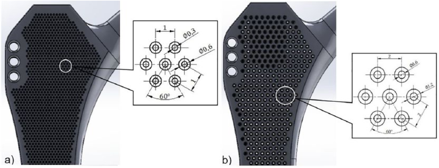
(a) Small pore (0.3 mm, KG) and (b) large pore (0.6 mm, BG) implants.
The inner region was created by subtracting a volume from the reference implant body. A Kubisch Raumzentrierten (KRZ) type lattice structure was applied to the subtracted volume in Netfabb®. By doing so, a porosity of 78.3% was achieved in the volume. Then, the surface-roughened hollow implant body and its inner region were combined together. The longitudinal section of the lightened implant is illustrated in Figure 4.

Lightening process of the implants.
Successfully designed implants were then imported into Magics® in order to adjust building orientation and create support structures. Each implant was placed on the virtual building platform with 10° angle to the

Positioning of the implants on the building platform.
In total, nine specimens (three of each 0.3 mm, 0.6 mm, and solid) were built using an EOS M280 direct metal laser sintering (DMLS) machine. All the specimens were annealed to stress relieving for 3 h at 650°C in an argon atmosphere after the DMLS process. Then, they were cut from the platform using a wire electrical discharge machine. Sandblasting with 3 bar pressure and duration of 10 min was applied to the specimens for deburring. In Figure 6, solid specimens (T1, T2, T3), large pore (0.6 mm) specimens (BG1, BG2, BG3) and small pore (0.3 mm) specimens (KG1, KG2, KG3) are shown together with the reference implant (O) produced by machining.

All implants prepared for the fatigue test.
Finite element analysis
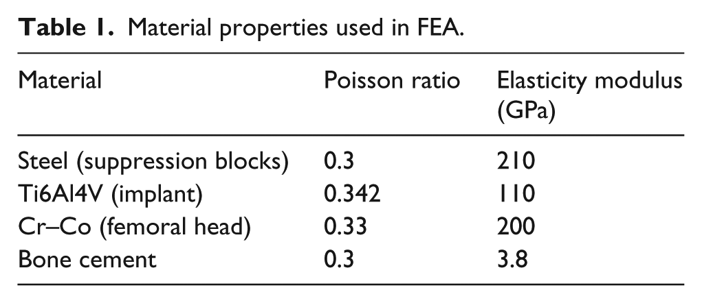
The finite element models were created in accordance with the requirements of ISO 7206-4:2010 standard using Ansys® Workbench 16.2 software. The finite element analysis (FEA) model includes two suppression blocks (transmit the loads to the stem), a femoral head and the implant embedded in cement 80 mm distance from the femoral head center with angle of 10° adduction and 9° flexion. For the aforementioned parts, the material properties used in FEA are given in Table 1.
Material properties used in FEA.
The bounded contact type was defined for bone cement–implant, conical head of the implant–inner surface of the femoral head, the outer surface of the femoral head, and the lower suppression interfaces. Furthermore, the contact type “no separation” was assigned between upper suppression block and the lower one. In addition, the bottom plane of the cement was described to be fixed support and the side surfaces of the upper suppression block was specified as frictionless support (Figure 7).

FEA model of the fatigue test.
All the parts in the FEA model were meshed using 10-node tetrahedral elements (SOLID187) and 20-node tetrahedral elements (SOLID186) included in Ansys® Workbench. The number of elements was increased in critical areas such as the implant neck and the contact surfaces to improve prediction accuracy. It is worth to note that the FEA model with solid implant has approximately 650,000 elements and the other ones, which contain lightened implants (pore sizes of 0.3 mm to 1 mm), have about 12,000,000–3,500,000 elements.
The sinusoidal load with a frequency of 15 Hz was acted vertically from the top surface of the upper suppression block to the femoral head center. The lower and upper force limits were 300 N and 2300 N (loading ratio: 0.1304), respectively. According the fatigue test standard mentioned in the previous section, the implants must withstand loads during 5 million cycles without any damage to be able to successful. The stress-life fatigue criterion and Goodman mean stress theory were used in FEA fatigue analyses. Since the multi-axial stresses might occur in the model during loading, the equivalent stresses were calculated according to the von-Mises yield criterion.
Fatigue tests
Fatigue tests of all the implants were performed on servo hydraulic fatigue test machine (Instron 8872) that has a 25 kN load and a 100 N m torque capacity at room temperature. The acrylic based bone cement, which is frequently preferred in THA and resistant to dynamic tests, was employed for fixing the implant in the defined position. The specimens were positioned in accordance with the aforementioned standard that provides maximum loading in the proximal femur region and allows the stem to be complexly loaded. 22 A gripping device (fixing clamp) shown in Figure 8 was used for positioning at the appropriate angles. Then, the specimens on the fixing clamp were placed in a stainless steel cup where bone cement was poured into.

Implant on the fixing clamp: sagittal plane view (a); frontal plane view (b); embedded implant in the bone cement (c).
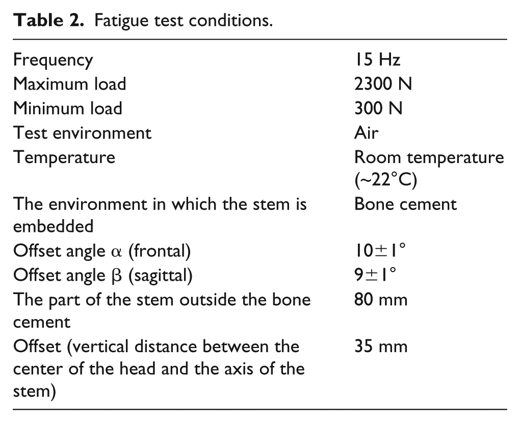
The sinusoidal compressive loads (with 15 Hz frequency and limits between 300 N and 2300 N) were applied to the implants during the test. The vertical displacements of the implants were measured via displacement sensor connected to an actuator in the test machine at every 50,000 load cycles. The detailed test conditions are given in Table 2.
Fatigue test conditions.
Results and discussion
The FEA for each designed implant are successfully completed and the vertical displacement, maximum equivalent stress and fatigue life results after 5 million load cycles are given in Table 3.
FEA results.

As expected, the displacements are directly proportional to the pore diameters on the implant surfaces. The reduction in the cross-sectional area with increasing pore diameter leads to higher displacements. It is worth noting that the deformation on the implants is in the elastic region.
The maximum equivalent stresses occur on the neck region of all implants. This observation is similar with the ones presented by Jameel et al. and Sivasankar.20,30 As seen in Table 3, the solid implant contains the smallest equivalent stress (211 MPa) compared to lightened ones. Additionally, lightened implants experience much bigger stresses under the same loading, which is due to the smaller and complex cross-sectional area. In addition, all the implants were found to be successful after five million load cycles. The fatigue life for all implants has been determined to be infinite.
The mean displacements in the implants during the fatigue tests versus number of cycles are illustrated in Figure 9. The reader may note that three fatigue tests for solid, BG, and KG implant types were completed and the mean displacement values for each group were then obtained by taking the average for each specimen data. Additionally, Table 4 includes a comparison between the measured mean displacements from fatigue tests and ones predicted by FEA. The mean displacements during the test for both solid implants (O and T group) are similar. The percent difference between them is only 2.97%. This means that DMLS is able to manufacture implants with sufficient fatigue performance compared with a machined one. On the other hand, it has been observed that BG and KG implants exhibit similar deflection during the tests. Implants with increased pore diameters cause 3.82% higher displacement values. However, the solid implants show lower displacement compared to the lightened ones. This verifies that solid implants have higher stiffness than lightened ones.

Mean displacement versus number of cycles.
Mean displacement values of specimen groups after 5x10⁶ load cycles.

Figure 10 shows FEA and measured mean displacements depending upon the pore diameters. The percent difference between FEA and test results are 1.5%, 12%, and 12.5% for solid, KG, and BG, respectively. Those differences might result from two issues. First, there are small regions that were not intended to be sintered during manufacture. As mentioned before, the lightened implant has a lattice structure inside and pores on the surface. Those structures have very small cross sections that are lower than the heat-affected zone diameter (Figure 11). This phenomenon could cause undesired sintered areas. The second is the force applied on the corresponding layer by the recoater blade while spreading the powder. The deflection of small and narrow angled sections by this force may cause small dimensional errors. Hence, the pores in the KG were only partially formed compared to the desired geometry, as can be seen in Figure 12(a). But the pores and cell development channels in the BG were successfully manufactured compared to the KG ones as the pore size of BG specimens was bigger than the KG ones (Figure 12(b)). It can also be noted that there are less partially sintered regions and that the deflections by recoater blade in the small sections are lower in BG specimens.

Comparison of FEA and fatigue test displacements according to the surface pore diameter.

Heat-affected zone formed around the laser beam.

Cell development channels of KG (a) and BG (b) hip implants.
In addition, all the implant masses were measured using a precision mass balance to determine the lightening rates. The measurement results are provided in Table 5. There is a small difference between the reference implant manufactured by machining and the solid one built via DMLS. This might be caused by the coating (thin hydroxyapatite layer), which has been performed by supplier, on the reference implant. However, there is no coating applied on the implants manufactured in this study. As expected, a lower mass in the lightened implants was obtained with a lightening rate of 14.81% and 16.97% for KG and BG, respectively. Further lightening of an implant might bring strength and stability issues, while less lightening could negatively affect the bone tissue development at the implantation region. Therefore, it is necessary to consider those situations in the lightweight implant designs.
Masses and lightening rates of the implants.

Conclusions
In this study, the implant geometry, which is widely used in THA, was determined according to the opinions of expert surgeons and faculty members. The chosen geometry was specially designed with surface pores and lightened by using the KRZ lattice structure. Thanks to the ability of additive manufacturing technologies that make it possible to build complex shaped and hollow parts, approximately 15–17% lighter implants were manufactured compared to solid ones with the same geometry. All the implants produced with DMLS have been shown to exhibit enough fatigue performance according to the requirements of the ISO 7206 standard. In addition, FEA findings are highly consistent with fatigue test results. Thus, the displacements outside of the investigated pore size range can be predicted with sufficient accuracy by FEA. This enables us to save production costs and obtain an idea about the implant performance without carrying out any building process.