
Abstract
Introduction
Additive manufacturing (AM) is gaining increasing importance in industry not just as a technology for prototyping but also, and in most cases, for the production of functional parts in different fields (1–2–3–4). One of the main advantages of AM is the design freedom to realize complex shapes. The global market for AM products and services has grown into a US $1.3 billion industry (2010 estimate) and is predicted to grow to over US $5 billion by 2020 (5). Among the different AM techniques, filament-based technology – i.e., fused deposition modeling (FDM) – is the most widely used, and it is also recognized as the best AM technique for functional structures (6).
FDM machines can be classified into 2 types: professional and consumer. The professional machines are those produced by the company Stratasys under the trade name Fortus® which, with its founder Scott Crump, developed the original FDM concepts. These machines can operate with acrylonitrile butadiene styrene (ABS) copolymer, nylon (Ny), polycarbonate (PC), and polycarbonate and ABS (PC-ABS), acrylonitrile styrene acrylate (ASA), polyetherimide (PEI) and polyphenylsulfone (PPSF). In recent years, many consumer machines have appeared on the market based on FDM working principles. Consumer machines can operate with poly(lactic acid) (PLA), ABS, polyethylene terephthalate glycol-modified (PETG), Ny and PC.
Turner et al (6) reviewed the principles of FDM and other extrusion AM processes. In this review, the process modeling and the science behind the deposition of the melt were discussed. The FDM process is controlled by many parameters which range from material filament type to machine setting, among them nozzle diameter and temperature, printing speed, feed rate, bed temperature, raster angle and width. Detailed studies are reported in the literature on the influence of printing settings (7–8–9–10–11). Es-Said et al (7) first studied the effect of raster orientation on mechanical properties, discussing the results in terms of polymer molecule alignment along the direction of deposition. Masood et al (8) studied the influence of raster width and raster angle on the tensile strength of PC-printed specimens, evidencing variation in the tensile strength when raster width varied from 0.4064 to 0.6064 mm. The highest tensile strength (58 MPa) was detected for samples printed with a 45°/-45° raster angle and a raster width of 0.6064 mm. Sood et al (9) reported that varying the raster angle from 60°/-30° to 90°/0° caused a decrease of 19% in tensile strength. Ahn et al (10) reported the use of a negative raster to raster air gap (RRAG) as an efficient method to obtain denser structure with an improvement of 30% in tensile strength. Hossain et al (11) carried out a detailed study on the improvement in tensile properties of FDM-manufactured structures by adjusting FDM processing parameters. They confirmed the relevance of the choice of a negative RRAG in the optimization of tensile strength (11), but the study lacked data on flexural behavior, relevant for many applications.
The development of innovative materials for FDM is gaining an increasing interest in various fields, with different perspectives which range from processing green filaments with wooden constituents (12, 13) to the use of composites (14) or high-performance polymers (15). The investigation of different materials for FDM filaments should extend the application of FDM techniques to unexplored fields in which the design freedom for complex shapes is an advantage – e.g., auxetic structures (16), thermal and acoustic insulation (17) and scaffolds for regenerative medicines that require personalized solutions together with more suitable materials (18, 19). Vaezi and Yang (20) discussed the potential of extrusion-based AM techniques with polyetheretherketone (PEEK) for biomedical applications, evidencing the difficulties of processing PEEK in FDM. PEEK is a valid alternative to implantable metal (e.g., stainless steel) because of its excellent biocompatibility combined with good strength and stiffness (21). In particular, PEEK's elastic modulus is similar to cortical bone (22), and its radiolucent behavior permits radiographic assessment (23). Oxford Performances Polymers (South Windsor, CT, USA) introduced onto the market the OXPEKK® material for 3-dimensional (3D) printing of orthopedic and neurological implants (24). Wu et al (25) stressed the decrease in the mechanical properties of PEEK when processed by FDM rather than by injection molding. Rahman et al (26) investigated the effect of raster angle on the mechanical properties of PEEK printed specimens. Cicala et al (27) extended the study of PEEK printed specimens using optimized formulations, comparing the results obtained to those of commercial and development materials and composites filled with carbonaceous and natural fillers (28). To date, in the scientific literature, only these papers have reported the investigation of PEEK as a possible material for FDM, despite the fact that PEEK is widely recognized as the polymer of choice for selective laser sintering in demanding applications.
The aim of the present study was twofold: an investigation of an industrial-graded PC in accordance with the previous literature (8), extending the study to flexural properties, comparing them with injection-molded specimens, as well; and characterization of innovative PEEK filaments on a prototypal FDM machine, comparing their mechanical properties with those of commercially available filaments.
MATERIALS and methods
Materials
An industrial-grade PC was purchased from Overmach, Italy; the PC considered is produced by Stratasys as filament for the FDM Fortus® 400 mc. An industrial-grade PEEK (melt volume rate = 35 cm3/10) was purchased from Luvocomm, Hamburg, Germany. For comparison, Ultra PLA, carbon polyamide (PA), poly(methyl methacrylate) (PMMA), and strong ABS filaments (Roboze, Bari, Italy) were also tested. All of the materials were used as received.
Materials processing
PEEK filaments were prepared in a single-screw extruder with screw diameter (D) of 20 mm and screw length of 25 × D (model E 20 TH; Collins). PEEK pellets were dried before use at 140°C for 48 hours; after that pellets were loaded in the extruder hood by using a volumetric feeder. The temperature pattern of the extruder was 55°C-350°C-355°C-360°C-370°C from input to output zones, the screw speed was set at 30 rpm, and the melt pressure, checked during all of the extrusion process, was 60 bar. An extruder head with a circular die (diameter = 3 mm) was used. The melted PEEK was drawn, cooling it with an air knife before collecting it on a rotating spool. The melt extruded filament, due to the drawing action of a rotating spool, varied in its diameter from 3 mm, at the exit of the extrusion head, to 1.75 ± 0.03 mm on the spool. The extruded PEEK filaments were processed by FDM, using a prototypal FDM machine Roboze one 400+ (Roboze, Bari, Italy) with the printing parameters, set by Cura software, as reported in Table I.
Printing parameters used for FDM-printed samples in PEEK and PC
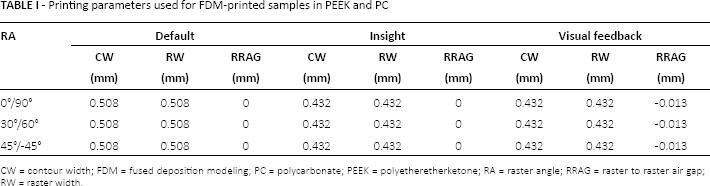
CW = contour width; FDM = fused deposition modeling; PC = polycarbonate; PEEK = polyetheretherketone; RA = raster angle; RRAG = raster to raster air gap; RW = raster width.
PC was received and used in the Stratasys® brand standard cartridge. For the production of the FDM-printed PC samples, a Fortus® 400 mc machine was used; the build orientation was flat on the XY build platform. The printing parameters used for PC are reported in Table I. The printing parameters used were selected in accordance with what has been previously reported in the literature for similar FDM systems (8). The printing parameters are represented in the schematic drawing in Figure 1 and reported in Table II, together with the code related to the different printing conditions.

Schematic view of the printing parameters.
Code for PC specimens printed using different conditions, and the related mechanical properties obtained in tensile and flexural tests
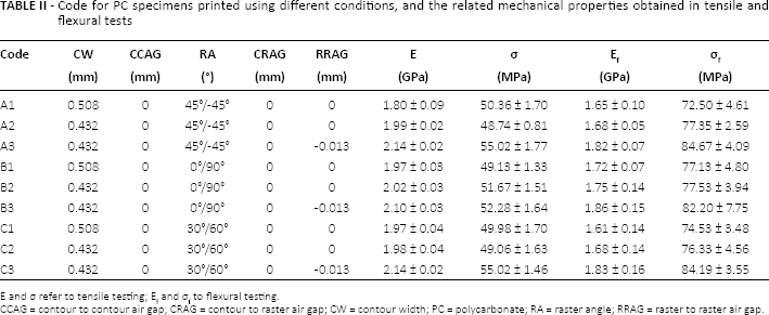
E and σ refer to tensile testing; Ef and σf to flexural testing.
CCAG = contour to contour air gap; CRAG = contour to raster air gap; CW = contour width; PC = polycarbonate; RA = raster angle; RRAG = raster to raster air gap.
All of the printed PEEK and PC specimens were prepared in accordance with the standards ASTM D638 and D790, for tensile and flexural testing, respectively.
PEEK pellets and PC pellets, obtained by pelletizing the PC filament obtained from Stratasys, were used to prepare, by injection molding, dog-bone specimens with dimensions according to ASTM D638. PEEK injection-molded specimens were obtained using a microinjection molder (Megatech H7/18-1) at 370°C melt temperature and 140°C mold temperature, with an injection and holding pressure of 16 bar. PC injection-molded specimens were fabricated using the same microinjection molder, at 270°C melt temperature and 100°C mold temperature, with an injection and holding pressure of 16 bar. PEEK and PC specimens were allowed to cool in the mold for 5 minutes before extraction.
Characterization
Tensile and flexural properties of the printed materials were investigated by testing 5 specimens for each kind of printed material under study. Tensile and flexural tests were performed using an Instron 5985 universal testing machine, equipped with a load cell of 10 kN. System control and data analysis were performed using Instron's Blue Hill software. ASTM D638 and ASTM D790 were applied for tensile and flexural tests, respectively.
Cryogenically fractured surfaces were analyzed with a EVO scanning electron microscope (EVO-SEM, Zeiss, Cambridge, England). SEM analysis was carried out on the surface of the as-printed specimens to unveil the presence of printing defects. All of the samples were gold sputter-coated up to a thickness of 20 nm (Emitech K-550 sputter coater; Ashford Kent, UK). An accelerating voltage of 15 kV was used to collect the micrographs.
Results and discussion
Mechanical properties of PC printed specimens: effect of printing parameters
The mechanical parameters obtained for the PC printed specimens, when tested in tensile and flexural modes, are reported in Table II and Figures 2 and 3. In particular, each mechanical property is related to the raster angle (Fig. 1), and for each raster angle, the results as they varied with the different printing methods are reported.
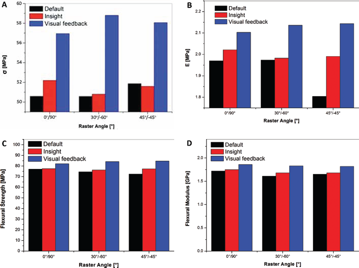
Mechanical properties for polycarbonate (PC) printed specimens versus raster angle for different printing methods: tensile strength (
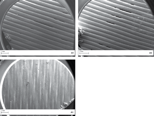
Scanning electron microscopy (SEM) images of polycarbonate (PC) specimens printed using different conditions (as reported in Tab. II). Scale bar: 1 mm.
The printing parameters showed a marked effect on the tensile properties (Tab. II; Fig. 2A, B) independently of the raster angle used. When a 0°/90° raster angle was used, e.g., the tensile strength increased from 49.13 to 52.28 MPa for samples printed according to the default and visual methods, respectively. For the same samples, the tensile modulus varied from 1.97 to 2.10 GPa.
The tensile results showed a similar trend compared with the studies reported previously in the literature (11), but the absolute values registered here were different from those measured with the same printing parameters. This difference could have been the result of the variation in the PC grade used between the 2 studies and of the effect of different machines printing the specimens. To the best of our knowledge, there is no study analyzing the variability of the mechanical properties from machine to machine, but the presence of such variation, due to the complex nature of the fusion and deposition process, can be assumed.
The flexural properties showed a similar trend (Tab. II, Fig. 2C, D), but the differences among the printing methods were less noticeable than for the tensile properties. For the samples printed with a raster angle of 0°/90°, the flexural strength varied from 77.13 to 82.20 MPa, while for the flexural modulus, the difference ranged between 1.72 and 1.86 GPa. In addition to that, the raster angle did not show a noteworthy effect for the different printing methods.
The high degree of differences exhibited in the tensile properties for PC can be explained as the result of the presence of a decreasing number of voids (Fig. 3) for the printed specimens (e.g., A1, A2, A3) when the printing parameters, especially the RRAG, were optimized (Tab. I). Decreasing the RRAG from 0 to -0.013 mm caused the disappearance of raster to raster voids. The change in the raster width from 0.508 to 0.432 mm (from default to insight method; Tab. I) did not have any appreciable effect on the presence of raster to raster voids. Nevertheless, it must be noted that even for the optimized sample, the analysis of cryogenically fractured cross-sections evidenced the presence of voids (Fig. 4). These voids are typical of FDM-printed specimens and are inevitable.
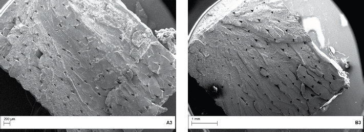
Scanning electron microscopy (SEM) images of the failure surfaces of polycarbonate (PC) specimens printed using different conditions (as reported in Tab. II). Scale bar: 200 μm (left), 1 mm (right).
Mechanical properties of PEEK printed specimens
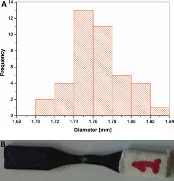
The filament diameters were checked (n = 40 measurements) before performing the PEEK printing, to ensure correct processing in the FDM machine. The analysis (Fig. 5A) showed an average diameter of 1.76 ± 0.03 mm. The filament here produced presented a diameter distribution similar to those of the best filaments available on the market. Tensile specimens were then prepared by FDM using a nozzle temperature of 420°C, higher than that used for the extrusion of the PEEK filament (i.e., 370°C). The nozzle temperature was set to a high value because of the need to melt the PEEK filament in the nozzle, in a short time, with no aid from mixing, as happens in the extruder. The quality of the PEEK printed specimens was good, as demonstrated by the optical analysis (Fig. 5B) and further confirmed by SEM analysis of the fractured specimens.
(
The tensile test results for the PEEK samples are summarized in Table III for all tested samples, and in Figure 6A, representative σ/ε curves are reported. The average tensile strength was 69.04 ± 7.01 MPa, and the tensile modulus 3.53 ± 0.01 GPa. Wu et al (25) reported for printed PEEK a maximum stress value of 56.6 MPa for samples printed with a raster angle of 0°/90°. Rahman et al (26) reported a maximum value of tensile strength of 74.49 MPa and tensile modulus of 2.8 GPa. However, these values referred to samples with all rasters aligned at a 0° angle and an infill density of 100%. Vaezi and Yang (20) studied the mechanical properties of PEEK printed specimens with infill density varying from 100% to 80%, showing tensile strengths of 75.06 and 49.22 MPa, respectively.
Roboze material properties and printing parameters compared with the innovative PEEK filaments
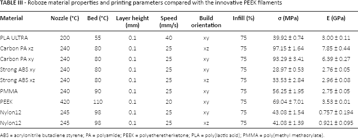
ABS = acrylonitrile butadiene styrene; PA = polyamide; PEEK = polyetheretherketone; PLA = poly(lactic acid); PMMA = poly(methyl methacrylate).

(
The failure surfaces of tensile-fractured specimens were analyzed by SEM (Fig. 6B). The rasters appeared to have been flattened to a thickness of 31 µm, with some rasters melted into a block. In contrast, Rahman et al (26) showed samples with rasters with a clear circular cross-section and very limited raster bonding. However, different from the PEEK printed in this present study, they used a nozzle temperature of 340°C with a bed platform of 230°C and nozzle diameter of 1.8 mm, and thus the limited raster bonding could be the consequence of the lower nozzle temperature used. Vaezi and Yang (20), who used printing conditions similar to those used here, reported tensile fractured surfaces comparable to the ones reported in Figure 6B. In addition, the failure surface (Fig. 6B) showed the presence of voids within some rasters, and, most relevant, raster pulling and rupturing can be observed. This finding partially contrasts with the results reported by Wu et al (25) which showed a higher degree of melting between the rasters.
Comparison among PC and PEEK printed specimens, injection-molded specimens and other materials
FDM is becoming much more relevant for functional applications. Stratasys, which is the product leader for FDM machines, constantly improves its applications, moving from the simple use of FDM for rapid prototyping to full exploitation as a manufacturing technology. For example, ABS, PC and PEI have been demonstrated to be useful to realize forming tools for both metal hydroforming and thermoforming. Ultem PEI (Stratasys®) has been reported to be a feasible material for small production runs (i.e., 500-1,000 parts) in the aerospace field (29). Other applications in satellites have also been reported (30) and in the biomedical field (31).
The use of FDM parts in functional applications is becoming an alternative to injection molding when a small to medium production rate is needed. To fully determine the potentiality of FDM manufacturing, in this present study, pelletized PC and PEEK filaments were processed in a standard injection molding machine. The mechanical properties of the injection-molded specimens are summarized in Figure 7. The tensile strength of FDM-printed PEEK was lower than that for injection-molded PEEK by 23.34%, while, for PC, the reduction was limited to 5.19%. The tensile modulus was less affected by the production technology, with drops of 3.29% and 6.96% for PEEK and PC, respectively. Similar results, for PEEK, were presented by Wu et al (25). In addition, SEM images (data not shown) exhibited the failure surface for the PEEK injection-molded tensile specimen; compared with the FDM-printed specimens, the surface appeared smooth, compact, dense and with no voids. The morphological aspect of the injection-molded specimens contributed to higher mechanical properties compared with the FDM specimens.
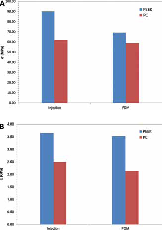
Mechanical properties for polyetheretherketone (PEEK) and polycarbonate (PC). Comparison between injection-molded and fused deposition modeling (FDM)–printed specimens: tensile strength (
(
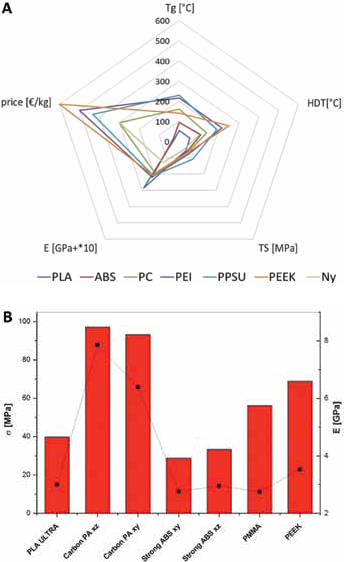
Despite the increasing use for functional applications, the Stratasys® FDM machines offer a limited choice of 7 materials: 5 grades of ABS, 1 grade of ASA, 2 grades of PC, 1 grade of PC-ABS, 2 grades of PEI, 2 grades of nylon and 1 grade of PPSU. The properties of Stratasys® materials were compared with those of the PEEK filament obtained here (Fig. 8A). The comparison showed that PEEK, with its Heat Distorsion Temperature (HDT) of 250°C, outperformed all other materials, showing mechanical properties similar to, or even higher than, PPSU, PEI and PC. Other engineering polymers – e.g., polyethersulphones (32), with interesting thermal properties, are not, to the best of our knowledge, available in filament form for the FDM-printing process.
A different comparison, with filaments offered by Stratasys for functional applications, is reported in Figure 8B for tensile properties only (Tab. III). PEEK, once again, showed higher tensile strength and modulus compared with neat polymers. However, Carbon PA presented better properties compared with PEEK, due to the presence of carbon fiber reinforcements in the Carbon PA formulation. As PEEK can be used as matrix for carbon-filled composite, the next steps will be a feasibility study of extruding Carbon/PEEK composite to verify its possible use for the FDM-printing process.
Conclusions
In this study, the effect of printing parameters on a professional grade PC printed with an industrial machine was studied first. The results confirmed the findings reported in the literature about the relevance of using a negative RRAG to optimize the tensile properties. In addition, this study verified that the similar effects on the flexural behavior were less marked than what found for tensile properties. This initial study was extended to a comparison of the properties of printed PC with samples manufactured by injection molding. The comparison demonstrated that, even if a professional industrial machine was used for printing, the FDM parts did not perform as well as those made by injection molding. These results were interpreted as the consequence of the less dense structure for FDM parts.
The first part of the study served as a sound basis for further investigation of a novel polymeric for possible use as FDM filament, as presented in this paper. The highlighted properties of PEEK filament and printed samples open new applications for FDM printing technology. Some defects in FDM-printed PEEK were evidenced, demonstrating that further research is needed to optimized the process, particularly in decreasing pore formation during the printing process. However, PEEK has favorable properties, including excellent mechanical properties compared with other filament materials including PC printed with industrial machines. On this last point, it is important to stress that the Roboze machine has a capital investment cost which is about 3 times less than that for an industrial Fortus machine. For that reason, PEEK should be a very promising material for industrial applications of 3D-printed components.