
Abstract
Introduction
With the exploitation of crude oil, there are more and more oil wells with high gas content in the oil fields that have been discovered or exploited. The biggest physical challenge of multiphase pump in oil and gas industry is the great change of gas volume fraction. Especially when the gas content is high, the gas compression process is no longer isothermal.Wet gas compression is considered to occur when the gas volume fraction (GVF) is 95% or above. 1 Wet gas compression causes a significant decrease in the volumetric efficiency of a pump and can be accompanied by serious vibration and thermal problems. The limited amount of liquid in the pump cannot absorb all the heat generated by gas compression, resulting in a sharp rise in the temperature difference between the inlet and outlet of the pump. During on-site operations, it has been found that the continuous working time of a twin-screw pump is less than 1 h when the GVF is 100%. 2
Chan 3 proposed two methods to improve the performance of a twin-screw pump under wet gas conditions. One is to increase the viscosity of the liquid. At high GVF, guar gum can be used to increase the liquid viscosity, which increases the flow of the pump. Second, the liquid can be directly injected into the pump shell. By selectively injecting the liquid into a specific pump cavity, the pressure distribution is better and the pressurization capacity is enhanced. Xu 4 proposed to inject liquid into the screw pump from the suction for the operating condition of wet gas compression, so as to improve the reliability and efficiency of the twin-screw multiphase pump. Müller-Link et al. 5 found that a twin-screw pump with a reflux circulation system can work normally even when the GVF exceeds 99.5%. Yang et al. 6 optimized the design of synchronous rotary multiphase pump and proposed that a wider but shorter cylinder can reduce the leakage caused by high gas content and is more suitable for the working conditions of higher inlet GVF. There have been a few reports on structural improvements for the problems caused by wet gas compression. To improve both efficiency and reliability of screw pump for high gas volume fraction, Bornemann 7 developed a “degressive screws”, but the specific design method and performance analysis were not reported in detail. A design for a multistage gradient decompressive screw pump was proposed in Ref., 2 but this approach is not applicable if the number of screw pump stages is less than 4.
Under wet gas compression, the temperature difference between the inlet and outlet of a screw pump increases sharply. The combined action of fluid pressure and temperature can lead to mechanical and thermal deformation of the rotor and liner. Deformation is an important factor affecting the volumetric efficiency and operational reliability of a screw pump. Räbiger et al. 8 studied the pumping characteristics and thermodynamic characteristics of screw pump with very high gas content through theoretical and experimental methods. It was found that when the gas content increases from 95% to 98%, the outlet temperature increases significantly. In Ref., 9 the deformation of a rotor in a twin-screw pump with high GVF was studied numerically.The results show that the deformation of screw rotor increases with the increase of air content. Lin et al. 10 carried out theoretical research on the screw temperature and the thermal deformation of a screw compressor, but the research only focused on the size of deformation. Yin et al. established a force deformation and thermal deformation model of the rotor of a twin-screw pump and studied the influence of high GVF on the rotor deformation and volumetric efficiency using a numerical calculation. 11 Based on fluid–structure coupling theory, Wei and Sun 12 studied the influence of fluid pressure and torque on the stress and deformation of a twin-screw rotor under different working conditions. Refs.13–15 studies the deformation law of screw motor and screw extruder under different working conditions and geometric parameters through fluid structure coupling simulation calculation. Kovacevic et al. 16 studied the fluid–solid interaction in a screw compressor. The temperature, pressure, and deformation of a rotor in an oil-free air compressor were calculated and analyzed by computational fluid dynamics software. Based on fluid–structure thermal coupling, Zhang et al. 17 analyzed the influence of high GVF on the comprehensive deformation of a rotor and liner and the volumetric efficiency of a twin-screw pump. They determined the optimal installation clearance. Reference 18 studied the effect of inlet GVF on the performance of a mixed transport pump and the internal gas–liquid two-phase distribution. However, most of the above studies consider only the influence of one factor on rotor deformation and ignore other factors. An analysis of the influence of only pressure or temperature cannot accurately determine the real deformation of a screw pump.
Therefore, based on the design characteristics of a twin-screw pump and screw compressor, this paper proposes a method for designing a decompression screw pump. The profile of the screw pump is fixed. According to the design concept of decompression in a screw compressor, the screw pitch and thread width of the screw rotor gradually reduce from the inlet to the outlet along the shaft direction. A fluid–solid thermal-coupling scheme is used to calculate the pressure and temperature distribution in a screw pump with the new structure and in one with a traditional structure. In addition, the deformation, outflow, and volumetric efficiency of the rotor and liner are determined. The purpose is to solve the problems of efficiency, vibration, and heat under wet gas compression.
Structural modification of a screw pump
The two-phase flow through a twin-screw pump is due to the axial movement of the medium from the inlet to the outlet, as shown in Figure 1. Because the density of the liquid is greater than that of the gas, then due to the centrifugal force during operation, the liquid is mainly outside the chamber and the gas is mainly inside the chamber. The chamber pressure increases continually from the inlet to the discharge. The gas is compressed in each stage, and its volume decreases. At the same time, due to the clearance between the rotors and the outer cylinder wall, the fluid can flow back from the high-pressure chamber into the low-pressure chamber. When the GVF is high, a large amount of liquid will flow back to the previous chamber, which is the main reason for the sharp decline in the efficiency of a twin-screw pump under wet gas compression.

Simplified flow through a multiphase twin-screw pump.
In this paper, the traditional screw pump described in Ref. 17 is optimized by using a decompressive variable-pitch screw rotor to solve the problems due to wet gas compression. The profile of the end face of the twin screws is fixed, but the screw pitch and thread width are gradually reduced from the inlet to the discharge along the axial direction. Thus, the volume gradually falls in the chamber to lessen the return flow. The shape of a helical rotor is generated by spirally sweeping a constant section profile along the pitch. The profile equation of the screw end face and the helix equation of a variable-pitch screw are introduced below. According to Ref., 17 the end face of a screw-pump rotor is a double cycloid, as shown in Figure 2.

Profile of the end face of a screw pump.
Since both sides of the double-cycloid tooth profile are completely symmetrical, only a one-sided profile equation is given. The basic equations for an epicycloid are
The curve equations for 

The curve equations for 


Here, the root circle radius,
The helix parameter equation for the variable pitch is derived as follows. In this design, the pitch 


The variable-pitch helix of a screw rotor is a continuous and smooth curve, which meets the following conditions:


Generation diagram of traditional screw rotor.

Generation diagram of variable-pitch screw rotor after modification.

Three-dimensional model of a decompressive variable-pitch screw pump.
Computational scheme
The solution methods of coupling problems are divided into direct coupling and sequential coupling. Due to more calculation, time-consuming and difficult convergence, direct coupling is rarely used in numerical calculation. Based on the structural characteristics and working conditions of the screw pump, this calculation adopts sequential coupling. In the WORKBENCH coupling calculation platform, firstly, the fluid domain of the twin-screw pump is solved by using FLUENT, and then the calculation results of the fluid domain (temperature and convective heat transfer coefficient) are applied to the coupling interface of the rotor and liner as external load to calculate the steady-state temperature distribution of the rotor and liner, Finally, the fluid pressure and temperature of rotor and liner are input into the structural static analysis module to calculate the comprehensive deformation of rotor and liner under fluid-solid-thermal coupling (as shown in Figure 6). This algorithm is especially suitable for solving complex coupling problems.

Coupling calculation process a-d of a decompressive variable-pitch screw pump.
Computational theory
Mathematical model of two-phase flow
The flow and heat transfer of a two-phase gas–liquid flow in a twin-screw pump is a multidimensional complex flow. The gas–liquid mixture not only undergoes complex turbulent motion, but also involves contact and heat transfer with the dynamic rotor and static liner. To establish a multiphase flow model of a twin-screw pump considering various factors, the following assumptions need to be made: (1) The oil and gas phases in a twin-screw pump do not permeate and mix with each other. (2) Each fluid phase has the same temperature fields. Also, the vapor phase of the oil and the influence of solid impurities are neglected. According to the above assumptions and the characteristics of fluid flow in a screw pump, the two-phase flow in the twin-screw pump uses a volume of fluid (VOF) model.
VOF model
The VOF model introduces the function 

Gas state equation
The gas in the twin-screw pump is compressible, and when the GVF is high, the limited amount of liquid in the pump cannot take away all the heat generated by gas compression. When that happens, the fluid in the pump is no longer regarded as isothermal compression. The gas state equation is :
Fluid–solid thermal-coupling model
The constraint equations for the solid and fluid in the coupling region are

With an increase of the GVF, the limited amount of liquid cannot take away all the heat generated by compression, and the temperature of the screw-pump rotor and liner will rise. Thermal deformation occurs due to the uneven change in the temperature in various parts of the screw pump. The temperature change will produce additional stress and strain in the material, causing the thermal expansion of the rotor and liner. The amount of thermal expansion is 
The geometric equations for normal strain and shear strain can be expressed as
By substituting Equation (15) into Equation (14), the coupled differential equations for temperature displacement in the rotor and liner plane can be derived as
Leakage mathematical model
The clearance of a twin-screw pump mainly includes the circumferential clearance between the rotor and the liner, the radial clearance between the rotor tooth top and the tooth root, and the flank clearance between the tooth sides. When two-phase flow is pumped, the leakage due to these various clearances depends not only on the chamber pressure difference, speed, and the geometric structure of the screw pump, but also on the GVF. To calculate the leakage after deformation, models for the leakage due to the three types of clearance will be established.
Due to the small gap between the rotor and the liner, the circumferential leakage can usually be regarded as slit flow between parallel plates, which is calculated as follows
11
:


The shape of the flank channel is very complex. To calculate the flank leakage, the flow is simplified as a flow through a rectangular channel, which is calculated as follows
11
:
Radial leakage can be regarded as a throttling process through an orifice. It is calculated as follows
11
:
The actual flow and theoretical flow through a screw pump are

The volumetric efficiency of the pump is
Boundary conditions and solver settings
Fluid domain
To improve the quality of mesh, a Hybrid Grid dominated by hexahedron mesh is used for 8-shaped fluid domain of screw pump, and tetrahedral mesh is used for rotor. The grid was densified at the boundary layer at the gap of the rotor and the junction of the spiral surface and inner and outer circles.There were 6.09 million cells in the fluid domain, and the calculated GVF was 96%. See Table 1 for the boundary conditions and solver settings.
Boundary conditions and solver settings.

Solid domain
Due to the complex structure of helical rotor, tetrahedral grid with strong adaptability is adopted to ensure the accuracy of calculation. The liner structure is regular, and the hexahedral grid is used, with the number of grid cells being 674266 and 403360, respectively.The materials of the rotor and liner were 38CrMoAl and 06Cr19Ni10, respectively. Their main performance parameters and boundary conditions are the same as those in Ref. 17 To allow a comparison of the calculated values with those in Ref., 17 the calculated fluid inlet temperature was fixed at 308 K. The outlet temperature was measured experimentally as 315 K.
Boundary conditions for the coupling region
The outer surface of the rotor and the inner surface of the liner were defined as the coupling surface. The flow heat transfer coefficient and the temperature of the near-wall surface of the rotor and liner obtained from the coupled calculation for the fluid domain were the boundary conditions for the coupling surface. The temperature field of the rotor and liner was then calculated, and the thermal deformation of the rotor and liner was calculated from the temperature field.
The fluid pressure calculated in the fluid domain was derived and applied to the coupling surface as a pressure load, which was used to calculate the pressure deformation of the rotor and liner. Moreover, the temperature, convective heat transfer coefficient, and pressure were used to calculate the comprehensive deformation of the rotor and liner.
The fluid–solid thermal coupling in a screw pump involves three coupling parameters: the surface temperature of the rotor and liner, the convective heat transfer coefficient, and the pressure of the fluid on the rotor and liner. The convective heat transfer coefficient and the pressure of the fluid were provided by FLUENT. The surface temperature of the rotor and liner was the temperature on the surface of the rotor and liner under fluid convection heat transfer. The numerical solution was provided by the solid-domain heat module.
Simulation results and analysis
Independence check of grid size
To check the independence of the fluid-domain grid, the numerical calculations were carried out with 2 million, 4 million, 6 million, or 6.5 million cells with a GVF of 96%. The pressure and volumetric flow are compared for different grids in Figures 7 and 8. As can be seen from Figure 7, there are no significant differences in the pressure in the screw pump for the different sizes of grid, and the pressure gradients are approximately the same. Moreover, Figure 8 shows that the volumetric flow hardly changed when the number of cells was increased from 6 million to 6.5 million. Therefore, this paper uses a grid with 6 095 522 cells for the subsequent numerical calculations.

Pressure along the rotor for different mesh numbers.

Volumetric flow vs mesh numbers.
Experimental verification
The clearance in the meshing area of the screw pump is very small, and its geometry is complex. Due to its high-speed rotation, the spatial position and geometry of the screw occasionally change, which makes it difficult to test the internal flow field in the screw-pump cavity. The external characteristics and performance of the screw pump were assessed experimentally to partially verify the numerical calculations for the three-field coupling interaction. Figure 9 shows the experimental setup for assessing the performance of a screw pump. The theoretical displacement of the centrifugal pump used in the experiment is 503/h and the rotating speed is 2900 r/min. The displacement of the air compressor is 0.9 m3/m. Table 2 lists the accuracy of the test instruments.

Schematic of the experimental setup for testing the performance of the screw pump.
Accuracy of test instruments.

In Ref., 19 when crude oil and natural gas were replaced by water and air as the test medium, the test results were similar. Therefore, in this paper, water and air are used as the working medium. In the experiment, firstly, the liquid is injected into the system through the liquid injection port on the liquid tank; Then, start the air compression pump to supply air to the system, and the gas and liquid will be depressurized through the pressure reducing valve on their respective pipelines, then pass through their respective measuring points and flow meters, and then enter the mixer for full mixing. The mixed gas-liquid two-phase fluid will be sucked into the pump by the screw pump, pressurized and discharged from the outlet. Pressure gauges and thermometers are installed at the inlet and outlet of the mixing pump, which can measure the pressure and temperature at the inlet and outlet when the mixing pump is running. Use the above instruments to measure the pressure, temperature and flow at the inlet and outlet respectively. During the experiment, after the system operates stably under various working conditions, the experimental data of each measuring point are recorded. The inlet and outlet temperatures of the screw pump, as measured by a thermometer, were used for the boundary conditions in the numerical calculations. The stop valve of the outlet pipeline of the screw pump was adjusted to change the pressure difference between the inlet and outlet to test the flow characteristics of the screw pump. The experimental values are compared with the numerical results in Figure 10.

Comparison of calculated and experimental values for the flow as a function of the pressure difference between the inlet and outlet.
As can be seen from Figure 10, the calculated flow for the pressure difference between the inlet and outlet has the same trend as the experimental values, which decreased with an increase of the pressure difference. When the pressure difference was less than 0.6 MPa, the experimental values were slightly higher than the calculated values. When the pressure difference was greater than 0.6 MPa, the experimental values were slightly lower. The average deviation is no more than 5%, which shows that the numerical results are consistent with the experimental values. Thus, this experiment verified the accuracy of this approach.
Comparative analysis of chamber pressure
Figure 11 shows the pressure distribution in the screw-pump cavity after optimization. The fluid pressure gradually increases from the inlet to the outlet. The pressurization near the outlet is faster than that in the middle chambers. The pressure difference between the two sides of the meshing area for the same axial cross section is obvious. Overall, the pressure distribution is basically the same as that of a traditional pump. Figure 12 compares the fluid pressure in the pump cavity before and after optimization. The data for the screw pump before optimization are from Ref. 17 The pressurization in all chambers of the optimized screw pump is higher than that of the traditional pump, and the pressure distribution is closer to being linear. This is because the volume from the inlet to the outlet decreases step by step, resulting in an increase of the pressure.

Pressure distribution in the chamber and a cross section of the screw pump after optimization.

Comparison of the pressure in each chamber of the screw pump before and after optimization.
Comparative analysis of chamber temperature
Figure 13 shows the fluid temperature in the chamber after optimization. The temperature gradually increases from the inlet to the outlet, with an overall rise of 7 K. The temperature gradient is shallow in the first two stages, with a temperature rise of about 4 K. The subsequent temperature rise was 3 K near the outlet of the last stage. Figure 14 compares the fluid temperature in the pump chamber before and after optimization. The temperature rise in the front chambers (about the first two-thirds of the rotor) of the traditional screw pump is relatively slow, with an overall temperature rise of about 8 K. The temperature rise in the last chamber is about 5 K. The trend for the fluid temperature in the screw pump is basically the same as that of the traditional pump. However, the temperature rise in each stage of the screw pump is significantly lower than in the traditional pump. Although the overall temperature rise is lower than that of the traditional pump, it is still a problem at high GVF due to wet gas compression. Thus, it is necessary to design a system to provide continuous cooling of the screw pump.

Fluid temperature distribution in the chamber of the screw pump after optimization.

Comparison of the temperature in each chamber of the screw pump before and after optimization.
Comparative analysis of volumetric efficiency
The flow through the traditional screw pump and the decompression screw pump were calculated for various values of the pressure difference between the inlet and outlet, as shown in Figure 15. The figure also shows the volumetric efficiency increase for the optimized pump. Since the chamber volume of the decompression screw pump gradually decreases from the inlet to the outlet, the return flow between the chambers is significantly reduced. As the pressure difference increases from 0.15 to 1.0 MPa, the propotion of volumetric efficiency increases from 7% to nearly 18%. Obviously, for an oil–gas mixed transportation system with high GVF, a decompression screw pump can solve the obvious reduction in volumetric efficiency in the structure.

Incremental flow through the screw pump before and after optimization and volumetric efficiency increase after optimization.
Comparative analysis of temperature field of rotor and liner
Figures 16 and 17 are the temperature distributions on the surface of the optimized screw rotor and on the inner surface of the liner, respectively, when the GVF is 96%. Like the traditional screw pump, the temperature of the rotor and liner increases gradually from the inlet to the outlet. The temperature of the decompression screw rotor and liner is different from that of the surrounding fluid (Figure 13). Due to the high GVF, the convective heat transfer capacity between the fluid and the rotor and liner is weakened. Therefore, the maximum temperature on the surface of the decompression screw rotor and liner is less than the maximum temperature in the fluid domain. The surface adjacent to the liner is mainly liquid, whereas the surface adjacent to the rotor is mainly gas. The liquid has a strong convective heat transfer capacity, so the surface temperature of the liner is slightly higher than that of the rotor, which is similar to the traditional pump. Moreover, Figure 18 shows that when the GVF is 96%, the temperature difference between the inlet and outlet of the rotor is about 6 K, which is lower than that of the traditional pump by 11 K. As shown in Figure 19, the temperature difference for the optimized liner is also significantly lower than before optimization. It is about 7 K before optimization and falls to about 4 after optimization K. Figure 20 shows that with an increase of the GVF, the temperature difference before and after optimization increases, but is significantly less after optimization than before optimization.
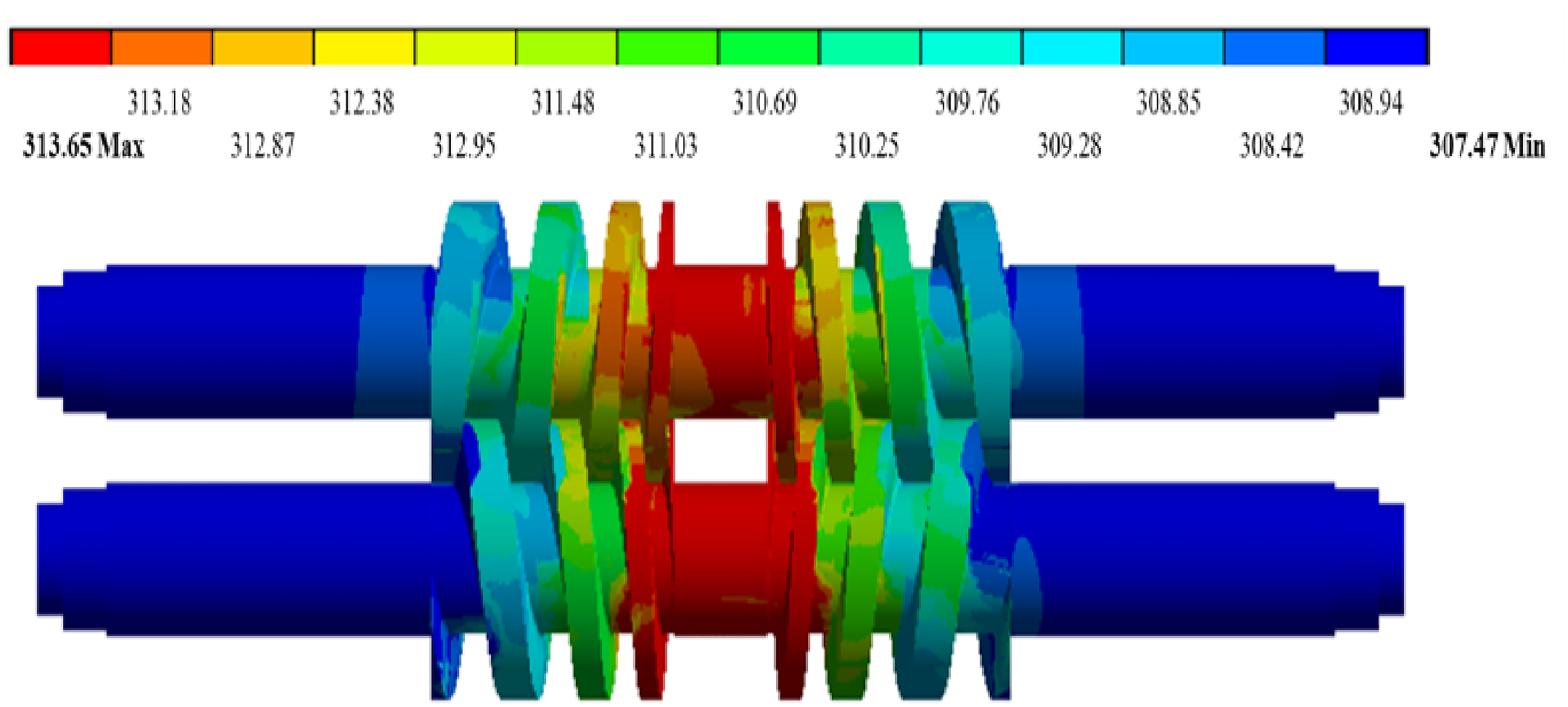
Temperature distribution on the surface of the rotor when the gvf is 96%.

Temperature distribution on the inner surface of the liner when the gvf is 96%.

Comparison of rotor temperature distributions.

Comparison of temperature distributions of the inner surface of the liner.

Comparison of influence of high gvf on temperature difference between inlet and outlet of rotor.
Comparative analysis of comprehensive deformation
Figures 21 and 22 show the deformation of the optimized screw rotor and liner in the radial, circumferential, and flank directions, respectively. As can be seen from Figure 21(a) and (b), the radial and circumferential deformations of the optimized rotor gradually increase from the inlet to the outlet, and the radial and circumferential deformations are approximately the same. In contrast, Figure 21(c) indicates that the flank deformation of the optimized rotor is opposite to the deformations in the radial and circumferential directions, as it gradually decreases from the inlet to the outlet. Figure 22(a) shows that the radial deformation of the optimized liner gradually increases from the inlet to the outlet, but it is not as uniform as that of the rotor. The deformation of the connecting part of the C-shaped area of the liner is smaller than in the other directions, and the maximum deformation occurs near the outlet. The magnitude of the radial deformation of the liner is larger than the magnitudes of the circumferential and the radial deformations and is also larger than those of the rotor. From the above analysis, it can be seen that the trends for the deformation of the rotor and liner of the screw pump are basically the same as those of the traditional pump. However, Figure 23 suggests that the magnitudes of the deformation in each direction differs. The figure compares the comprehensive deformation between the radial, circumferential and flank directions of the decompression screw pump and the traditional pump from the inlet to the outlet. The magnitudes of the deformation in each direction are smaller for the screw pump than for the traditional pump, mainly because the elastic deformation is smaller than the thermal deformation, and the total deformation from the inlet to the outlet is due to expansion. Because the increases in temperature from the inlet to the outlet and for each chamber of the decompressive screw pump are less than those of the traditional pump, the deformations in the three directions are less than those of the traditional pump.

Comprehensive deformation of the rotor in (a) radial, (b) circumferential, and (c) flank directions.

Comprehensive deformation of the inner surface of the liner in (a) radial, (b) circumferential, and (c) flank directions.

Comparison of (a) radial, (b) circumferential, and (c) flank deformations before and after optimization.
Comparative analysis of the change in the clearance
Figure 24 compares the clearance of the screw pump from the inlet to the outlet before and after optimization. The radial and circumferential clearances of the two screw pumps gradually decrease from the inlet to the outlet. This is because the temperature increases along the outlet direction of the screw pump, the expansion deformation gradually increases, and so the clearance gradually decreases. The radial and circumferential clearances of the optimized screw pump are larger than those of the traditional screw pump. This is mainly because the temperature rise in the decompression screw pump is smaller than that in the traditional pump. Thus, the expansion deformation is smaller, so the clearance is higher. Since the expansion deformation is in the same direction for the male and female rotors, the flank clearances of both pumps decrease slightly, and there is no obvious change in the flank clearance.

Comparison of (a) radial, (b) circumferential, and (c) flank clearances before and after optimization.
Comparison of effects of GVF on volumetric efficiency
Figure 25 compares the volumetric efficiency before and after optimization of the screw pump as the GVF increases from 90% to 99%. The pressure difference between the inlet and outlet is 1.0 MPa. As the GVF changes from 90% to 95%, the volumetric efficiency gradually increases. It then decreases rapidly to a minimum near 98% before increasing slightly. This is because when GVF is lower than 95%, circumferential and radial expansion increases with the increase of GVF, which helps to reduce leakage. When GVF exceeds 95%, the flank leakage increases rapidly, and the volumetric efficiency of the pump decreases sharply. When the gas content is greater than 98%, due to the gas reflux at the outlet, the pressure difference between the outlet and the adjacent chamber decreases, which is conducive to reducing leakage, so the efficiency is improved.The trend of volumetric efficiency with GVF is basically the same before and after optimization. It is significantly higher after optimization than before optimization. The average increase in the volumetric efficiency is about 14 percentage points.

Comparison of influence of gvf on volumetric efficiency before and after optimization.
Conclusions
(1) To solve the problems caused by wet gas compression, such as the efficiency decline, vibration, and heat, a method for improving the design of a decompression screw with variable pitch is proposed in this paper based on the characteristics of a twin-screw pump and screw compressor. A fluid–solid thermal-coupling model is established. ANSYS WORKBENCH was used to calculate the pressure, temperature, deformation, flow, and volumetric efficiency of the rotor and liner of an optimized screw pump and a traditional screw pump. Compared with the experimental results, the average error for the flow was less than 5%.
(2) The fluid temperature in the screw pump increases gradually from the inlet to the outlet, with a total temperature rise of 7 K. The temperature rise increases slowly by about 4 K in the first two stages. It increases rapidly near the outlet of the last stage, with an increase of 3 K. The trend for the fluid temperature of the improved screw pump is the same as that of the traditional pump, but the temperature rise in each chamber is significantly lower than in the traditional screw pump. The trends for the radial, circumferential, and flank deformations of the decompression screw rotor and the liner are basically the same as those of the traditional pump, but the magnitudes of the deformation in the three directions are less than those of the traditional pump. For a pressure difference between the inlet and outlet of 1 MPa, as the GVF increases from 95% to 99%, the maximum increase in the volumetric efficiency is about 18 percentage points and the average increase is about 14 percentage points. The decompression screw pump can fundamentally solve the decline of the volume efficiency at high GVF, and appropriately reduce the temperature rise between the inlet and outlet.But the problem of vibration and noise still exists.