
Abstract
Introduction
Membrane structures are widely used in long-span buildings such as stadiums and warehouses. There are two kinds of membranes: one is homogeneous membrane such as ethylene tetrafluoroethylene (ETFE) membrane and the other is coated fabric membrane such as polyester fabric coated with polyvinyl chloride (PES/PVC).
Different from homogeneous materials, the internal structures of coated fabric membranes are complex, which prompts coated fabric membrane’s mechanical behavior to be more complicated than homogeneous materials. Temperature, humidity, loading history, and service time all have significant impacts on mechanical properties of the coated fabric membrane. 1 Uhlemann 2 have researched the tensile behavior of the PES/PVC membrane and the G/PTFE membrane. There is no apparent difference in Young’s modulus between the PES/PVC and the G/PTFE membrane, although the initial Young’s modulus of the G/PTFE membrane is higher than the former. The elastic property of the coating fabric membrane is determined by the fabric and the coating themselves and the manufacturing process of them. In all of these, the additional tension applied to the fabric during the manufacturing process is important, too. Given by existing studies, the shear modulus of the coated fabric membrane is smaller than its Young’s modulus, and only 0.05–0.03 times of the Young’s modulus in the warp direction.1,3,4 The shear deformation has a great influence on the forming of the tension membrane structure. 5 The shear modulus of the coated fabric can be obtained by biaxial tensile test or frame test. 6 Shi et al. 7 researched the shear stress-strain relationship of the coated fabric membrane by biaxial tensile test.
The coated fabric will wrinkle under the compressive stress. Thus, in the practical engineering, the coated fabric is usually biaxial tensioned. Since the yarns in the fabric are intertwined, when the yarns in the load direction are straightened, the yarns in the other direction will be significantly curled. Consequently, the mechanical behavior, the damage and fracture behavior of the coated fabric are different from the laminates remarkably. A series of strength criteria are commonly used to predict the strength of the orthotropic composite material, such as Hashin criterion, Tsai-Hill criterion, and Tsai-Wu criterion.8–10 Those criteria are based on the test of non-crimp long-fiber composites such as prepreg board or laminate. The results of biaxial tensile test can describe the mechanical properties of the coated fabric. Galliot and Luchsinger 6 proposed a strength model for coated fabric which based on biaxial tests. The model has high precision, but the parameters of the model need to be obtained by biaxial tensile tests in five different load cases. Uniaxial tensile strength data is also commonly used in the design of membrane structures. The off-axial tensile test refers to stretching the specimen not along the warp or weft direction of the coated fabric membrane. In the off-axial test, the coated fabric membrane deforms in both warp and weft directions. Therefore, the off-axial test can be used to research the properties of the coated fabric membrane bearing multiaxial stress. Zhang et al. 11 researched the off-axial tensile strength of the coated fabric membrane and used Tsai-Hill criterion to describe the off-axial strength of the coated fabric membranes. Ye 12 explored the tensile strength of the membrane at different off-axis angles. Colman 13 used uniaxial tensile test data to establish the viscoelastic model of coated fabric subjected to reciprocating multiaxial tensile and shear loads. In the design of membrane structure, the ratio of the maximum principal stress to the weft stress of the coated fabric membrane was used to check whether the membrane structure is safe.14,15 In the meantime, the strength theory of the coated fabric membrane is mostly through biaxial test.
Compared to the uniaxial test, the biaxial test is expensive and complex. In multiaxial tensile tests, coated fabric membrane specimens usually break from parts outside the biaxial tension zone, such as the edge of the specimens. The multiaxial strength of the coated fabric can be predicted according to the uniaxial tensile test data. Dinh et al. 16 proposed a model which can predict and estimate the nonlinear, orthotropic and permanent deformation of the coating fabric membrane by uniaxial and biaxial tensile tests. However, the model demand eleven parameters, four of these need to be obtained through complex biaxial tensile test. Aboshio et al. 17 worked on the uniaxial strength of the neoprene coated nylon fabric, and used this data to predict the blasting strength. In Aboshio’s research, it proves that the uniaxial tensile test data of the coated fabric membranes can also be used to accurately predict the multiaxial failure loads of the membranes.
Membrane structures need to maintain good performance in a wide variety of environments. Ma 18 researched the tensile strength of the coated fabric membrane material at high temperature, and gave the formula for it. Zhang et al. 19 compared the tensile strength, Young’s modulus, and elongation at break of PTFE membrane from −20°C to 70°C and proposed the influence coefficient of temperature on the mechanical property of coated fabric. Li 20 researched the uniaxial tensile strength of coated fabric membrane between 0°C and 80°C. Wu 21 investigated the mechanical properties of the membrane after a long time of natural exposure in cold regions.
The existing studies are mainly concerned with the nonlinear mechanical behavior of coated fabrics at high temperature. The Murnaghan nonlinear elastic constitutive model usually used in metals is now used in coated fabric, which has been proposed according to the research on the nonlinear property of PVDF coated fabric between −30°C and 70°C by Ambroziak and Kłosowski. 22 Zhang et al.23,24 researched the visco-elastic behaviors of the PVC coated fabrics by creep test, relaxation test, and cyclic loading test. Zhang et al. 25 proposed that the elastic modulus linear decreased during temperature increased. There are few design codes of fire-resistant design of membrane structures because the strength of the coated fabric at high temperature hasn’t been well studied. At present, the high temperature properties of the coated fabrics are not studied comprehensively. At present, there is no research on biaxial tensile test of membrane materials at high temperature, so the uniaxial tensile test is still an important method for the strength research of membrane materials. Sun et al. 26 researched mechanical property of different brands of coated fabrics at high temperature and proposed a method for estimating the strength of coated fabrics in high temperature environment. Sun found that the relationship between strength and temperature of the coated fabric produced by different companies is similar. Yu et al. 27 researched the strength of coated fabric from 20°C to 170°C and proposed the linear decrease model of the coated fabric strength at high temperature. Zhang et al. 28 researched the multiaxial strength at different temperatures by biaxial tensile test and proposed the Tsai-Hill criterion can be used to estimate the strength of coated fabric bearing off-axial stress at high temperature.
The membrane structure is usually composed of several pieces of membranes, and typically connected by stitched joint, welding joint, glue joint, or special connector. Weld joint is heavily used because it is water resistant and easy to operate. Sometimes, the structures may failure at the joint. Hollande et al. 29 researched the peeling strength of weld joint which welded by high-frequency welding and then gave the influence of welding temperature and pressure on weld strength. Shi 30 researched the strength and the deformation behavior of weld joints on airship-using coated fabric membranes with different welding techniques. Cui 31 and Qing et al. 32 have obtained the minimum lap length required for the welding of coated fabric membrane.
When the coated fabric membranes were welded, the coatings melt and permeate each other, the fabric does not melt during welding. Thus, the strength of the weld seam is lower than that of the membrane. In the event of a fire, the structure may fracture at the welding joint, but there is only little research on the mechanical behavior of the weld joint of PVC coated fabric at high temperature. Zhao et al. 33 researched the strength of weld joint and obtained the strength of weld seams at temperature between 20°C and 70°C and proposed the minimum lap width which can meet the design strength requirements at 70°C. There is no research about the strength of weld joint of PVC coated PES fabric. It is necessary to establish the strength model of coated fabric membrane and its joints at high temperature to achieve the fire-resistant design of the membrane structure.
High temperature can soften the coating and the fabric, thus changes the mechanical properties of the coated fabric significantly. The surface temperature of the membrane structure can reach 70°C under the sunlight in tropical countries 1 and it will catch fire when the temperature exceeds 250°C. Therefore, the study of the strength of coated fabric membrane under high temperature condition is urgently needed.
Strength of coated fabric membrane at high temperature
With the increasing of temperature, the strength of the coating material and fabrics witness a significant decrease, so it is necessary to research the strength of coated fabric.
Warp and weft strength of coated fabric membranes at high temperature
Experiments layout
In this experiment, the HYTEX PVC coated plain woven PES fabric made by HONGYUAN CORPORATION was used. The thickness of the coated fabric is 1.04 mm while the total weight is 1300 g/m2. The allowable strength provided by the manufacture is 140 kN/m in warp and weft direction.
The experiment method suggested by Coated Fabrics for Membrane Structures was followed to the experiment.
34
The specimens were cut along the warp and weft direction of the membrane. As shown in Figure 1(a), the size of the specimen is 1100 mm × 50 mm. The length of the holding part is 500 mm, while the testing part is 100 mm long. The

Specimen of tensile test: (a) size and shape of specimens and (b) principle of tensile test.
The specimen was fixed in the test machine at first step. Then, adjust the test machine to the predetermined temperature and keep it for 10 min to ensure that the temperature of the specimen is even. After the temperature distribution of the specimen was consistent, the specimen begins to be stretched at a rate of 25 mm/min until it breaks. The test machine needs to be fully cooled after each specimen was tested. Six working conditions were considered for the high temperature test of membrane, including 23°C, 70°C, 90°C, 110°C, 130°C, and 150°C. The coating will be chapping and falling from the fabric when temperatures above 150°C, thus, the maximum temperature in this study was set at 150°C. Two specimens were tested in each working condition with the same test methods.
Experimental result
The fractured specimen is shown in Figure 2. As illustrated, the fracture surface of the specimen was neat at 23°C. At 70°C and higher temperatures, significant crimp appeared at the fracture surface (Figure 2(b) and (c)). When the temperature was below 110°C, fibers fell off from the edge of the specimen (Figure 2(d)). When the temperature was 130°C and 150°C, yarns fell off from the edge of the specimen (Figure 2(e) and (f)). When the temperature is higher than 130°C, the coating becomes debris and falls off from the specimen. The results of the conditions from warp and weft direction are similar.

The warp-direction specimens after fracture: (a) 23°C, (b) 70°C, (c) 90°C, (d) 110°C, (e) 130°C, and (f) 150°C.
The stress-strain curves of specimens along the warp and weft direction is shown in Figure 3(a) and (b). The stress-strain curve of fabric has obvious nonlinearity. The stiffness of coated fabric increases as the strain increases. The strength of specimens shows rapid decline with the increasing temperature.

The stress-strain curve: (a) warp direction and (b) weft direction.
Experimental analysis
Coated fabric of the same strength level from different companies usually has different thicknesses. The strength of a fabric is typically expressed by the tensile strength that can be withstood per meter width. The strength of coated fabric in different temperature were shown in Figure 4. The standard deviations of the specimens were moved 5°C to the right to prevent the symbols overlapping. The weft-direction strength is lower than the warp-direction strength at all temperatures. Although the strength in both directions sees a decrease with the increasing of temperature, the weft-direction strength decreases more obviously. According to the test, the strength in warp direction of coated fabric decreased 28.6% when the temperature change from 23°C to 150°C, while the strength in weft direction decreased 41.1%. By statistical analysis of ANOVA tests, the

Strength of coated fabrics at different temperatures.
The strength of the coated fabric membrane in warp and weft direction at different temperatures can be expressed as:

where
Off-axis strength of coated fabric membrane at high temperature
The strength of the coated fabric depends mainly on the fabric. The fabric has significant anisotropy and a small shear stiffness. When the membranes bear off-axis loads, significant shear deformation occurs in membrane. This means that the stiffness of coated fabric along off-axis direction is significantly lower than which in warp or weft direction. Affected by both high temperature and off-axis load, the structure may undergo large deformation or failure.
Experimental layout
As illustrated in Figure 5, the shape and the size of the off-axis tensile test specimens are as same as the one used in warp tensile test but the former one was cut along the warp direction at

The off-axis specimens after fracture: (a) straight fracture surface and (b) jagged fracture surface.
Experimental result
As the off-axis angle gets closer and closer to 45°, the stiffness and strength of the coated fabric membrane decrease gradually, while the fracture deformation and transverse deformation increases. Although the loading direction is not parallel to the warp or weft direction, the fracture still occurs along the warp or weft direction. Most specimens broken only along warp or weft direction. A few specimens torn along weft direction at first and then along the warp direction when the crack spreads to the edge of the specimen. The maximum loading occurs at the beginning of crack and then the load is already quite small by the time the crack turns. The straight fracture surface is shown in Figure 5(a) while the jagged fracture surface is shown in Figure 5(b).
Only a few fibers were pulled out on the fracture surface when the temperature was lower than 110°C. Some yarns were pulled out when the test temperature was 130°C.
Experimental analysis
The strength of coated fabric membranes at different off-axis angle and temperature was shown in Figure 6. The off-axial strength of coated fabric decreases as the off-axial angle tend to 45°. When the off-axis angle was less than 15°, the tensile strength of coated fabrics changes significantly with the off-axis angle. The effect of temperature on the tensile strength of coated fabric membrane is more remarkable when there was a large off-axis angle. The off-axial strength at 23°C along 5° and 35° off-axis angle is 84.6% and 58.4% of the warp-direction strength. However, when the temperature rises to 130°C, this tensile strength becomes 35.2% and 12.82% of the warp-direction strength. Multifactor variance analysis was used to analyzes the result. The

Strength of coated fabric membranes at different off-axis angle and temperature.
The strength of coated fabric membrane can be expressed by:

where
Strength criteria for off-axis coated fabric membranes at high temperature
The fracture surface was parallel to the warp or weft direction when the membrane bearing the biaxial load. 35 Thus, only stress in potential fracture surface need be checked. According to the reciprocal law of shear stress, the shear stress in the warp-direction sections is equal to the normal stress in the weft direction. It also applies to the weft-direction sections. The stress was decomposed into warp direction and weft direction:

The strength of coated fabric bearing off-axis load can be expressed by:

Parameters

At present, the commonly used strength criteria of coated fabric membrane include maximum principal stress criterion and Tsai-Hill criterion. The maximum principal stress criterion is the most widely used strength criterion currently and recommended by Technical Specification for Membrane Structures by CECS. 14 Strength of off-axial test and theoretical values of different strength criteria was shown in Figure 7. The strength of coated fabric whose off-axis angle in the range from 20° to 70° will be underestimated if the maximum principal stress criterion was used. Tsai-Hill criterion can accurately estimate the mechanical behavior of the coated fabric membrane with an off-axis angle in the range from 15° to 75°. Equation (6) can be used to estimate the strength of coated fabric membrane with an off-axis angle from 5° to 85° in different temperatures.

Experimental and theoretical values of off-axis strength.
Strength of weld joint of coated fabric membrane at high temperature
Membrane structure buildings are often made of pieces of membranes. Common joining methods of membranes include stitched joint, welding joint, bonding joint, and splinting joint. The weld joint is widely used in membrane structures because the weld joint is waterproof and easy to produce. Common welding methods include single butt welds, double butt welds, and lap welds. The most common welding method in engineering is lap weld.
Weld strength in parallel to direction of warp or weft
Experiment layout
The test was followed the method suggested by Coated Fabrics for Membrane Structure.
36
Two types of weld joints were tested: weld joints parallel with the warp direction and parallel with the weft direction. The membrane was cut and welded at first. The welding temperature was set at 210°C and the welding time was 30 s. Membranes with welding joint were cut into specimens after the welding seam were fully cooled. The size and structure of the specimens were shown in Figure 8. The width, length, and lap length were 50, 150, and 50 mm, respectively. The specimen was held by the capstan grips and the holding part was 500 mm long.

Weld joint specimen of coated fabric membrane.
The test procedure and temperature are described above. Two specimens were tested in each working condition.
Experimental result
Peeling of weld seam or fracture of membrane near the weld seam are two common types of weld failure. Sometimes, both modes occur in one specimen. The failure mode of all weld joint is peeling failure but significant damage still appears in the membrane near the weld joint when the temperature was 23°C. All fracture surfaces show no difference in appearance when the temperatures higher than 70°C. There was no difference between weld joints parallel with the warp direction and weft direction.
Experimental analysis
The uniaxial tensile strength of weld joint specimens at different temperatures was shown in Figure 9. With the temperature increases, the strength of the weld decreases significantly. When the temperature changed from 23°C to 130°C, the maximum tensile load of weld specimens decreased from 5420 to 540 N. The error bar were moved 5°C to the right to prevent the symbols overlapping. The statistical analysis was performed through ANOVA tests and the

Strength of weld joint and warp-direction membrane at different temperatures.
The strength of weld joints at high temperature can be expressed by:

where
In Figure 9, the sensitivity of weld joint strength to temperature was much higher than that of membrane. From 23°C to 130°C, the strength of the weld joint decreased by 91% while the strength of membrane along warp direction only decreased by 26%.
The ratio of the strength of membrane and weld joint was 0.81 at 23°C and 0.11 at 130°C. The strength of weld joint cannot meet the requirement of design code when the temperature is higher than 110°C. The strength ratio of weld joint to membrane can be expressed by:

where
Only the coating melts and penetrates each other when the membrane was welded. The fibers in the fabric are not connected. Therefore, there is no difference between weld joints parallel to warp and weft direction.
Strength of asymmetrically weld joints
Perpendicular experimental layout
Membranes were cut and welded at first. One was cut along the warp direction. The other was cut along the line apart the asymmetrically angle from the warp direction. The welding temperature was 210°C and welding for 30 s. Membranes with weld joint were cut into specimens after the weld joint was fully cooled. The size and structure of the specimen is as same as the one shown in Figure 8. The width of the specimen was 50 mm. The length of the test part and the lap length was 150 and 50 mm, respectively. The specimen was held by the capstan grips and the holding part was 500 mm long. Finally, set the same working temperature as above for the test. There are three types of asymmetrically angle which were set to 5°, 15°, and 35°. Two specimens were tested in each working condition.
Experimental result
Specimens with different asymmetric angles under the load of 2000 N were shown in Figure 10. Three different asymmetric angle welding joints all show disharmony deformation. Different Poisson’s ratio on both sides of the weld leads the remarkable difference deform on both sides of the weld.

Asymmetric weld joint specimen with 2000 N load: (a) 5°, (b) 15°, and (c) 35°.
No matter the temperature is below or above 90°C, the failure mode of weld is peeling failure. However, the membrane has obvious damage when it is below 90°C. When the temperature is higher than 90°C, the membrane damage is obvious only at the 35° asymmetry angle.
Experimental analysis
Figure 11 shows the strength trend of specimens. The results show that the strength of asymmetric weld joint decreases significantly with the increase of temperature. The statistical analysis was performed through ANOVA tests method. The

Strength of asymmetric weld joint.
The strength of asymmetric weld joints can be expressed by:

Where
Peeling strength of weld joint at high temperature
Peeling test of weld joints was carried out by loading the weld seam along the plane normal direction of the weld. The average loading of the peeling test is the peeling strength. The load state similar to the peeling test rarely appears in actual engineering. However, the results of the peeling test are not affected by the lap length, the width of specimens, and other factors, which can reflect the mechanical properties of the weld seam stably. Therefore, the peeling test is still an important method to evaluate the quality of weld seam. The principle of peeling test is shown in Figure 12(a).

Specimen of peeling test: (a) size and shape of specimens and (b) principle of peeling test.
Experimental layout
The test followed the method suggested by Coated Fabrics for Membrane Structure. 37 The specimen has the same size was shown in Figure 12(b). In the test, the membrane was held by capstan grips. The test equipment was be pretreated as described above. The experimental conditions are also set as in the previous experiments. Two specimens were tested in each working condition.
Experimental result
In the peeling test, the load increases approximately linearly at first and then enters the stable peeling stage after reaching the maximum value. In the stable peeling phase, the load fluctuates within a range, but the maximum loading during the peeling process is less than that at the beginning of peeling. The load-displacement curves of the peeling test were shown in Figure 13. The load-displacement curves fluctuated with a period of about 2 mm, which were consistent with the width of the yarn. Peeling force reaches the peak when the front edge of fracture was between the two yarns and reaches its minimum when the front edge of fracture on the center of the yarn. Both the peak and average peeling force decreased significantly as the temperature increased.

Load-displacement curve in the peeling test.
Experimental analysis
Before the weld seam started to fail, the work done by the testing machine on the specimen was converted into the elastic strain energy of the specimen. The force was approximately constant in the stable peeling phase so there was no change in the elastic energy. The work done by the load resulted in the tearing of the coating at the weld and the formation of a new surface. The fracture energy of a weld refers to the energy required to form a new surface. The fracture energy of weld joints can be expressed by:

where
At the beginning and end of the test, the specimen was not loaded, and there was no obvious residual deformation after the test. Thus, all the work of loading was used to form the fracture surface. The work of loading can be expressed by:
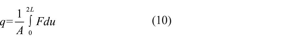
Where
Fracture energy of weld joint at different temperatures was shown in Figure 14. The standard deviation of the specimens were moved 5°C to the right to prevent the symbols overlapping.

Fracture energy of weld seam at different temperature.
As illustrated, the peeling energy of weld seams decreases linearly with the increasing of temperature. The statistical analysis was performed through ANOVA tests and the
The peeling energy at different temperatures can be solved by:
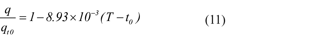
Where
The peeling energy decreased linearly with the temperature increasing. When the temperature is higher than 130°C, the peeling strength is too low to measure and the weld has completely lost its bearing capacity.
Conclusion
This paper serves as an introduction to the strength of coated fabric and weld joint of coated fabrics at high temperature. By testing and comparing the strength of coated fabric, the models to estimate the strength of coated fabric bearing uniaxial load and multiaxial load at high temperature was proposed. Methods to estimate the strength of weld joint of coated fabric have also been proposed, too.
The specific conclusion about coated fabrics is as follows:
The warp-direction strength and weft-direction strength of the coated fabric decrease significantly at high temperature. The warp and weft strength of the coated fabric decreases linearly with temperature. The weft-direction strength decreased more significantly. Compared to the strength of membrane at 23°C, the strength decreased 28% in warp direction and 41% in weft direction at 150°C.
Off-axis strength of coated fabric strength is lower than warp-direction strength and weft-direction. Tsai-Hill criterion can be used to estimate the strength of coated fabric when the off-axis angle is greater than 15° but it will overestimate the strength of coated fabric bearing small off-axis load. The strength model proposed in this paper can better predict the strength of coated fabric membrane at a small off-axis angle.
The specific conclusion about weld joint of coated fabrics is as follows:
The strength of the weld joint is lower than the membrane and it is more sensitive to the change of temperature. The weld joint loses the bearing capacity completely when the temperature is higher than 130°C while the strength of coated fabric only decreased 21.3%. Membrane structures may be damaged at welded joints when it was exposed to fire.
There is an additional transverse shear stress in the weld seam when asymmetric weld joint is loaded, which results in the strength of asymmetrical weld joints being lower than that of symmetrical weld joints. The strength of the welded joint with a 35° asymmetric angle is only 41% of the symmetrical one.
The peeling energy of the weld joint decreased linearly as the temperature increased. There is a linear correlation between tensile strength and peel strength of welded joints. Peeling energy can be used to estimate the tensile strength.
Based on the above conclusions, the strength reduction caused by high temperature should be carefully considered in the fire resistance design of membrane structures. Now that the strength of the welded joints at high temperatures is much lower than that of the coated fabric, special attention should be paid to checking the fire resistance of the welded joints or to using additional fire protection measures at the welded joints.