
Abstract
Keywords
Introduction
Serial robot manipulators have been widely used in manufacturing, aerospace, and logistics industries due to their simple mechanisms, large workspaces, and flexible operations. Performance analysis of manipulators is the prerequisite for the mechanism design, actuator selection and matching, operating style assessment, and motion planning and control. Manipulability measures based on performance analysis provide useful information for the quantification of robot’s inherent properties and for the assessment of robot motion, and hence they are used to construct the objective functions in the mathematical models of robot design and motion planning. Some crucial performance metrics to which should be pay special attention in the process of robot development and use mainly include the kinematic, mechanical, and dynamic capabilities of the robot. The kinematic capability usually refers to the dexterousness which is used to identify the manipulator’s capability to generate velocities in various directions of the task space under the constraints coming from the joint velocity limits. Kinematic capability reflects the velocity transmission ratio of robot manipulator from joint space to task space. The mechanical capability of a robot manipulator for a given configuration is defined as the maximum forces that can be applied by the robot end-effector in any directions of the task space with the restricts of the actuator limits and joint velocity and acceleration limits. The dynamic capability of a robot is the ability of its end-effector to perform accelerations in arbitrary directions of task space, which is used to evaluate the mapping from joint driving space to task space with the consideration of the joint torque and velocity limits and the effects of the gravity and end-effector payload. The aim of this article is to provide a general method applicable to the computation of these three widely used performance metrics.
In the context of manipulability analysis, several approaches have been proposed, such as the traditional or improved manipulability ellipsoids and polytopes. Yoshikawa 1 proposed the concept “manipulability measure” applicable to both redundant and nonredundant manipulators and established a control algorithm for singularity avoidance of redundant manipulator and obstacle avoidance. Yoshikawa 2 also investigated some properties of the manipulability measure and introduced the first definition of the manipulability ellipsoid. Moreover, the total manipulability measure of robotic manipulators was separated into translational and rotational manipulability in Yoshikawa’s research. 3 Vahrenkamp and Asfour 4 proposed an extension to the Yoshikawa’s 2 manipulability ellipsoid measure. Their extended manipulability measure incorporated the joint limits and the self-distance between the manipulator and other parts of the robot and was used to represent the capability distribution in the robot’s workspace. The aforementioned studies mainly focused on the kinematic manipulability ellipsoid obtained by the application of the singular value decomposition of the Jacobian matrix relating the joint velocities to the end-effector velocities. In fact, the kinematic manipulability ellipsoid approach maps a unit sphere constrained by the normalized joint velocity limits in actuator space to an ellipsoid bounding the end-effector velocity in any direction of task space. Since the manipulability ellipsoid method is inexact in transforming the joint limits into task space, Lee 5 used polytope to quantify the motion capability of a robot and proposed a practical method to construct the exact manipulability polytope. Manipulability polytope method has been used for velocity workspace analysis for multiple arm robotic system in Lee’s research, 6 in which the problem of the difference and asymmetry of joint limits has been considered and handled. In recent research, Jaquier et al. 7 achieved geometry-aware manipulability learning, tracking, and transfer. They established a novel manipulability transfer framework and provided a way by which robots can learn and reproduce manipulability ellipsoid from expert demonstrations. Choi et al. 8 proposed a simple desired manipulability ellipsoid used for generating the motion of a manipulator with its trajectory and determining its optimal posture.
Some approaches have also been proposed in the literature to measure the force or mechanical capability of robot manipulators. In Chiu’s work, 9 force manipulability ellipsoid was used for measuring the capability of manipulator postures and matching the manipulator’s posture to the task requirements. Chiacchio et al. 10 proposed an algorithm to correctly evaluate the force manipulability polytope in task space and a new definition of the force manipulability ellipsoid. Their work focused on the static force capability for redundant manipulators. Okabe 11 investigated the translating manipulability polytope of kinematic redundant manipulator and discovered that the translation vector is a function of velocity and acceleration of the extended task space. Nokleby et al. 12 provided a methodology that allows for the actuator limits and includes both analytical and optimization-based methods to determine the force capability of nonredundantly and redundantly actuated parallel manipulators. Finotello et al. 13 used their proposed polytope method in which the translational and rotational analyses are separated to analyze the kinetostatic performances of robot manipulators. Mahjoub and Fahim 14 took the effect of the gravity into the static behavior analysis of robot manipulators and then integrated the generalized weight that represents the gravity-induced forces acting on individual links of robot with the force ellipsoid to obtain the true force that a manipulator can apply in its task space. Chiacchio et al. 15 demonstrated that the gravitational forces embedded into the derivation of the ellipsoid can produce a translation of the ellipsoid along all task space directions rather than cause a compression in the ellipsoid volume. Wei and Gao 16,17 proposed an approach to calculate the output force capacity polytope of multi-degree-of-freedom (DOF) manipulators based on the linear programming method and the geometric method and used their introduced approach to generate the output force capacity polytope and select the driving parameters for a three-DOF excavating manipulator.
When performing kinematic and static manipulability analysis, we neglect the manipulator dynamics. However, in some cases where the robot manipulator must work in the heavy-load, high-speed, and high-precision situations, the manipulator dynamics cannot be completely ignored. Yoshikawa 18 firstly proposed the concept of dynamic manipulability measure with the consideration of the manipulator dynamics to measure the manipulating ability of the robot end-effector. In Chiacchio and Concilio’s work, 19,20 a new definition of manipulability ellipsoid that can lead to more correct results and can be used for the case of singular configuration was given to evaluate manipulating capability in terms of end-effector accelerations for redundant manipulators. Rosenstein and Grupen 21 demonstrated that the internal motion of a manipulator and its end-effector movement have a complex and nonnegligible effect on dynamic manipulability. Yokokohji et al. 22 extended the dynamic manipulability ellipsoid to the dynamic performance analysis of multifingered grasping systems. Their research proved that the internal forces affect both the volume and the offset of the manipulability ellipsoid bounded the end-effector accelerations, while the gravity forces only lead to an offset of the manipulability ellipsoid. Similar conclusions about the influence of gravity on the dynamic manipulability ellipsoid have also been given by Chiacchio et al. 15 Zou et al. 23 used convex polytope method to quantify the dynamic manipulating capability of a hydraulic manipulator in terms of end-effector forces. Zhou et al. 24 conducted the dynamic manipulability analysis using ellipsoid method for multiarm space robot and further extended their method to the closed-loop system composed of the space robot and the captured target. In their research, dynamic manipulability measure was obtained based on dynamic manipulability factor and dynamic manipulability ellipsoid, and the effects of some dynamics parameters, joint variables, and structural geometry parameters on the dynamic manipulability measure were investigated. Chen et al. 25 proposed a dynamic manipulability measure method to assess the unfixed manipulation of an object using multiarm space robot through frictional contacts. Azad et al. 26 studied the effects of the weighting matrix on dynamic manipulability of robots.
In the existing work mentioned above, the three categories of manipulability are analyzed, respectively, by their corresponding methods. There is still no one method that is generally suitable for kinematic, mechanical, and dynamic manipulability. In addition, some dynamics constraints, nonlinear items, and the applicability to both redundant and nonredundant manipulators have not been systematically and adequately taken into account. In this article, we introduce a general method for performance analysis of serial robot manipulators using the manipulability polytope which is a convex feasible region defined by the joint constraints and manipulator kinematics and dynamics. Compared with previous studies, our method is universal for quantifying the end-effector manipulability in terms of velocities, forces, and accelerations in various directions of task space for both redundant and nonredundant serial manipulators. Kinematic manipulability is analyzed by constructing task-space velocity polytope based on kinematic equations, while mechanical and dynamic manipulability analyses are conducted by defining task-space force and acceleration polytopes based on dynamic equations, respectively. When investigating the end-effector accelerations, the influences of Coriolis and centrifugal forces, gravity, and payload are taken into account. In the case of end-effector force capability evaluation, the effects of joint accelerations, gravity, and Coriolis and centrifugal forces are considered. Nonlinear items are handled by linear approximation method, to make it convenient for defining task-space polytopes using feasible region construction method, which is a more generic way for the manipulator with asymmetric joint constraints and redundant DOFs. Moreover, a systematic architecture and detailed procedures are necessary for performance computation with respect to different types of manipulability of serial robot manipulators. Finally, our proposed method is applied to two numerical examples, namely, two- and three-DOF planar manipulators, and it is proven correct and effective.
The remainder of this article includes (1) the basic statement and mathematical models of several manipulator manipulability computation problems; (2) the proposed polytope method for manipulability analysis in terms of task-space velocities, accelerations, and forces; (3) the performance analysis architecture and procedures applicable to any given configuration, end-effector operating trajectories, and entire workspace of a manipulator; (4) two case studies for assessing the performance of two- and three-DOF planar manipulators. Finally, the conclusions are drawn.
Problem statement
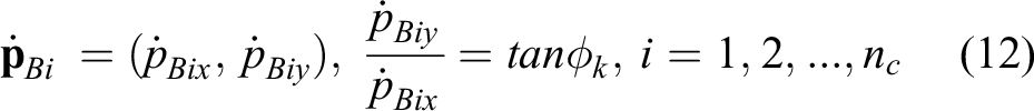
The goal of this research is to quantify and characterize the manipulability of serial robot manipulators in task space, including the capabilities of manipulator to generate end-effector velocities, forces, and accelerations in various directions. End-effector output performance is determined mainly by the input joint velocities or driving torques of the joint space, but the end-effector payload, gravity, and some nonlinear terms in dynamic equations also have nonnegligible effects on the mechanical and dynamic capability. Such influence factors arising from driving capability of joint actuators and dynamic behavior of manipulator have to be considered thoroughly and handled effectively to obtain more accurate and realistic manipulator performance.
Robot manipulator transforms the driving velocities or forces provided by the actuators into the task velocities, forces, and accelerations. Thus, as the base of the performance computation, manipulator’s kinematic and dynamic models must be established. For a serial manipulator with


In above equations (1) to (3),
Combining equations (2) and (3), the end-effector acceleration vector can be further solved as

The forces manipulator that can apply in task space can also be given as

Considering the constraints of the joint velocity limits, a mathematical computation model of the end-effector velocity in any direction of the task space can be formulated as

where
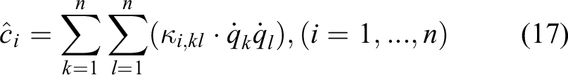
When investigating the end-effector acceleration performance, an optimization problem subject to maximizing the magnitude of the acceleration can be given as

where
Similarly, to identify the manipulator’s capability to apply force in any direction of task space, an optimization-based mathematical model can also be formulated as

where
In the above optimization models, the transformation relationship between the joint space and the end-effector task space is established. It is clear that equations (1), (4) and (5) are the implicit equality constraints of equations (6), (7) and (8), respectively. The optimization-based mathematical models can easily reveal that manipulability analysis for robot manipulators is to calculate the end-effector output capability for velocities, accelerations, and forces in various directions under the joint driving capability limitations and the robot kinematics and dynamics constraints. These models have an advantage on the revelation of the physical significance, but their solving processes are the time-consuming and tedious undertakings. Especially, some challenges caused by the nonlinear terms included in the dynamics constraints cannot be effectively tackled with the existing ellipsoid and polytope methods.
Proposed method
In this section, a systemic and general method to identify the mechanical and motion capability of a serial manipulator in its output space is introduced in detail based on the feasible region construction method of the linear programming problem. A linearization method of the nonlinear terms in the dynamic equations of a manipulator is presented to simplify the manipulability polytope construction. Several typical problems in manipulability polytope construction such as redundant actuation, singular configuration, and asymmetric joint constraints are also discussed.
Feasible region construction method for determining manipulability
To give a better introduction of the application of the feasible region construction method to the manipulability analysis, a methodology of using it to analyze the kinematic and static performance is presented firstly. Kinematic performance analysis is used to determine the end-effector velocity capability under the known joint velocity constraints, as formulated in equations (1) and (6). The feasible region of the end-effector velocity is a vector set of the maximum allowable velocities in various directions of the output space, and it can be defined as

In the static performance analysis problem, manipulator capability to apply forces in different directions of end-effector output space is to be found with the constraints of the maximum allowable actuated torques or forces. Compared with the dynamic performance analysis, inertial force and Coriolis and centrifugal forces included in equation (5) are ignored in static force capability calculation. Thus, the feasible region of the end-effector forces manipulator can apply can be described by

In equation (10), the term represents the effect of gravity is not included, and it will be considered in the manner of feasible region translation when conducting the force capability analysis.
According to equation (4), a relation between the end-effector accelerations and the actuated joint torques can be established as

In equation (11), the terms arise due to the end-effector payloads, Coriolis and gravity, and other inertia forces are not considered to ensure the relation has a linear form. When carrying out the dynamic performance analysis, all those ignored terms will be added.
For a planar robot, its end-effector has a two-dimensional output space, that is,

The feasible region of the end-effector velocity
The polytope constructing method given above can provide an effective mean for manipulator performance visualization, but it cannot directly quantify the manipulator capability in various directions except for those at the vertices of the polytope. Since the manipulator capability to generate velocity in any direction can be characterized by the distance from the origin of the reference frame to the point on the boundary of the polytope in corresponding direction, velocity performance of entire output space can also be obtained by computing the distances in various direction angles
where

where


Computation of performance in any direction.
Based on equations (10) and (11), the end-effector force and acceleration polytopes only determined by the actuated joint torques can also be constructed by using the above method. However, it is clear from equations (4) and (5) that only the mapping between the end-effector force/acceleration and the actuated joint torques cannot exactly reflect the manipulator output capability. According to equation (5), the end-effector force can be rewritten as

Where
For a given manipulator configuration, the effect due to the gravity is a fixed value which will translate the center of the polytope away from the origin where

The set
Unfortunately, the elements of
where

Therefore, the end-effector polytope characterizes that the manipulator’s capability to apply the forces in different directions is the sum of the bias due to the gravity and the polytopes determined, respectively, by the actuated joint torques, joint accelerations, and joint velocities. The values of the points on the boundaries of the above constructed polytopes can be calculated by the similar method used to obtain the boundary values of the end-effector velocity polytope as given in equations (12) to (14).
Here, the acceleration polytope in the output space is also constructed using the similar method. It is assumed that the end-effector payload is determinate when computing the end-effector accelerations. To determine the acceleration feasible region in task space corresponding to the joint actuated torque limits and the joint velocity limits, equation (4) is rearranged as

where

where

Moreover, the final end-effector acceleration polytope is obtained by translating an overall displacement determined by the end-effector payload and the gravity on the basis of the sum polytope constructed by the actuated joint torque constraints and the joint velocity limits as given in equations (11) and (21).
Linearization method for the joint velocity items in dynamic equations
It has been presented that each element of the vectors representing the effect of the joint velocities is nonlinear and dependent with each other when calculating the end-effector forces and accelerations. For the expressions
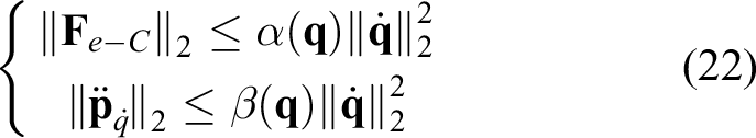
where both
As equations (18) and (21) expressed, once the lower and upper bounds of
(1) The extreme points are the intersection points of the joint velocity limits. In this case, the extreme points are selected from the combinations of the joint velocity limits. For an
(2) The extreme points are exactly selected from the stationary points. In this case, for each element of
(3) The extreme points are located on the convex or concave boundaries of the allowable region defined by the joint velocity limits. In this case, some elements of the extreme points are the upper or lower bounds of the joint velocities, and the others are those whose first partial derivatives are zero. Assuming that the number of the equations
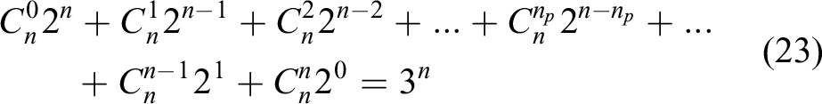
Obviously, this case includes the two cases mentioned previously: in case (1), the number of extreme points is
Considering
Analysis of several typical cases
To enhance the generality of the proposed method, several typical problems may encounter in performance analysis, such as the redundancy of the serial manipulator, singular configuration, and asymmetric joint actuated velocity or torque constraints, which are discussed in detail in this section.
Analysis of a case with redundancy
For a redundantly actuated serial manipulator, let
There is also another method to solve the problem of manipulability analysis of redundant manipulator, namely, linear combination or projection-based method, as shown in studies by Lee
5
and Wei and Gao.
16,17
In Lee’s research, manipulability polytope was constructed by linear combination of column vectors of Jacobian matrix or by projecting the joint constraint into a plane made of row vectors of Jacobian matrix. To avoid the incorrectness due to the pseudo-inverse of the Jacobian of redundant manipulator, Lee’s method can be used to construct the end-effector velocity polytope defined by equations (9) and the end-effector acceleration polytopes defined by equations (11) and (21), and the item
Analysis of a case with singularity
When a nonredundant manipulator is in a singular configuration, the Jacobian
Analysis of a case with asymmetric joint constraints
In the traditional methods, whatever the ellipsoid or polytope, the joint limits are normalized in the unitary way even though the lower and upper limits of each joint are asymmetric. In this case, the asymmetric joint limits must be transformed to the formulations which are easy to be described in the normalized way. Then, the augmented matrix or the scaled Jacobian obtained by multiplying the Jacobian matrix with the diagonal matrix whose elements are specified by the arguments is used to replace the Jacobian matrix to develop the relation between the joint space and the task space. Through the augmented matrix, the admission joint actuated velocity or torque spaces described by the unit hyperspheres (for ellipsoid method) or hypercubes (for polytope method) are transformed into the hyperellipsoids or polytopes in task space. In our method, the joint limits are directly substituted into the constraint equations to construct the end-effector feasible output space; thus, it is not necessary to handle the asymmetric joint limits using the unitary way. Similarly, even though the lower and upper bounds of
Performance analysis architecture and procedures
Based on our proposed general performance analysis method, an overall architecture applicable to manipulability assessment for any given posture, practical or simulated end-effector operating trajectories, and entire workspace of a robot manipulator is established, as shown in Figure 3.
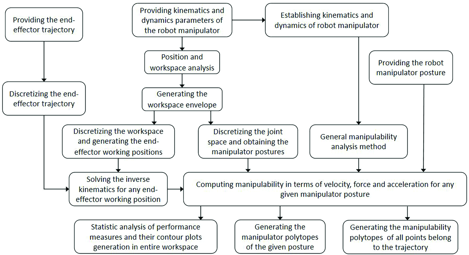
Architecture for performance analysis.
Performance analysis as illustrated in Figure 3 is performed by a computer program, in which algorithm with respect to each module listed in the architecture is developed. The main procedures for performing evaluation are outlined in the following steps. Initialization: Give the kinematics and dynamics parameters of the robot manipulator, the end-effector trajectory and manipulator postures, the manipulator motion characteristics, and the external loads acting on the manipulator Kinematics and dynamics modeling: Establish the manipulator’s kinematics and dynamics models based on the parameters given in the previous step. The manipulator end-effector position can be described by applying the Denavit and Hartenberg (D-H) procedure and the matrix transformation method. Furthermore, the manipulator’s motion equations including kinematic and dynamic equations can be obtained by using the algorithm of Newton–Euler’s formulation. Position and workspace analysis. The position of the points on the manipulator mechanism is related to the joint angles. The relation between the position of any point and the joint angles is defined based on the D-H coordinate system transformation. Workspace boundary is determined by the maximum reachable range of the manipulator end-effector, which is related to the joint angle limits. Workspace envelope is drawn by position and workspace analysis. Trajectory, joint space and workspace discretization. The given trajectory is firstly discretized into a series of end-effector working points, then manipulator postures corresponding to each end-effector point belongs to the trajectory are solving. There are two methods to obtain the discretized series of end-effector working points in workspace. One is to obtain the end-effector working points in workspace by discretizing joint angles and direct position analysis, the other is to generate working points through uniformly discretizing the domain enveloped by the workspace boundary. In the former case, the obtained end-effector working points are disorderly and randomly distributed in the workspace, but a one-to-one correspondence between the working points and the postures is established. On the contrary, in the latter case, the obtained working points are uniformly and orderly distributed in the workspace, but each working point corresponds to many or even infinite postures obtained by inverse kinematics analysis. Inverse kinematics solving: Conduct inverse kinematics analysis for all the working points included in the given trajectory or obtained by workspace discretization. A series of manipulator postures and end-effector orientations corresponding to each working point are obtained to prepare for performance analysis. General manipulability analysis method programming: Develop computer program modules for general manipulability analysis based on our proposed method and established architecture (Figure 3). Manipulability computation: Computing manipulability measures and construct output polytopes for the postures which can be arbitrarily specified or obtained by discretizing joint space or solving inverse kinematics for discretized working points in workspace in terms of end-effector velocities, forces and accelerations. Visualization and statistic analysis of manipulator performance: Visualizing the performance of the manipulator postures which belong to the trajectory or correspond to any working point by manipulability polytopes, and then performing statistic analysis for the manipulability measures of each working points and generating performance spectrum plots for the manipulability measures in the entire workspace.
Case studies
To demonstrate and confirm the correctness and effectiveness of our proposed methodology, two practical applications for performance analysis, respectively, of two- and three-DOF planar manipulators are used in this section. The details on the computation of the matrices and vectors included in the manipulator kinematics and dynamics, which support the performance analysis, can be seen in Appendices 1 and 2.
Case 1: A two-DOF planar manipulator
The parameters used for numerical simulation of a two-DOF manipulator are provided in Table 1. Now, enough foundation is established to evaluate the manipulator’s manipulability to perform. Our objective is to show how to use our proposed method and established architecture as stated in previous sections to analyze the manipulator’s manipulability for any given posture, operating or simulated trajectories and the entire workspace in terms of end-effector velocities, forces and accelerations.
The parameters used for numerical simulation of a two-DOF manipulator.

DOF: degree of freedom.
Figures 4 and 5 show the manipulator’s capability to generate velocities in various directions along the horizontal and arc trajectories, respectively. Each end-effector working point on the trajectories corresponds to two manipulator postures, except for those not only on the workspace boundary but also corresponding to the singular postures or those in the domain in which one of two postures corresponding to any working point cannot be achieved due to the joint limits. Comparing the polytopes generated by our proposed method with the traditional ellipsoids, it can be seen that the ellipsoids contained as subdomains of the polytopes underestimate the achievable end-effector velocities. Two manipulator postures corresponding to the same working point have different capability to generate velocities in task space. In Figure 4, both polytopes and ellipsoids become narrow gradually in horizontal direction with the unfolding of the manipulator. Until the joint angle between the two links of the manipulator reaches zero, the polytope together with the ellipsoid degenerate into two segments, respectively. In Figure 5(a), the first type of manipulator posture cannot reach the top domain of the workspace due to the joint limits. Similarly, the second type of manipulator posture cannot reach the bottom domain of the workspace as shown in Figure 5(b). In Figure 5, it can also be seen that the manipulator postures achieve the given arc trajectory have the same capability to apply velocities in various directions of the task space, when the joint angles between the two links of these postures are the same.

Velocity manipulability ellipsoids (blue) and polytopes (red) of different operating postures for a horizontal trajectory. Workspace boundary (gray).

Velocity manipulability ellipsoids (blue) and polytopes (red) of different operating postures for an arc trajectory. Workspace boundary (gray).
Figure 6 shows the spectrum plots of two performance measures for two type of manipulator postures. One measure

Spectrum plots of velocity performance measures for two type of manipulator postures.)
In the force output capability analysis, the lower and upper bounds of the joint accelerations are, respectively, assigned as

End-effector force manipulability ellipsoids (a) and polytopes (b) for the posture
The end-effector force manipulability ellipsoids and polytopes plots given by Figure 8 show the output capability difference between the two types of operating styles for a horizontal trajectory. It is clear that the force capability manipulator can provide in horizontal direction increases gradually with the unfolding of the manipulator, while those in vertical direction decrease slightly. In fact, when the two links of the manipulator are collinear, which is a singular posture, the maximum forces manipulator can apply in a horizontal direction to overcome the external loads no longer depend on the limits of the joint actuating torques but on the manipulator structure strength, at the same time the maximum vertical forces the manipulator can apply are defined by the joint torque limits and the length of the links.

End-effector force manipulability ellipsoids and polytopes of different operating postures for a horizontal trajectory.
The resulting ellipsoids and polytopes to quantify the force output capability of two type of operating styles for an arc trajectory are plotted in Figure 9. It can clearly be seen that two operating styles can provide different force output capability. The postures with the same joint angles between the two links have the same force output capability in task space. Furthermore, for a given working point, the optimal operating postures can be selected from the two operating styles according to the demands of the objects or task.

End-effector force manipulability ellipsoids and polytopes of different operating postures for an arc trajectory.
The spectrum plots of force performance measure quantifying the directional uniformity of the force capability for two type of manipulator postures are shown in Figure 10. Similar to the spectrum plots of the velocity performance measure
Spectrum plots of force performance measures for two types of manipulator postures.
Figure 11 shows the acceleration manipulability ellipsoids and polytopes corresponding to the manipulator posture

End-effector acceleration manipulability ellipsoids (a) and polytopes (b) for the posture
Figures 12 and 13 show how the manipulator postures affect the end-effector acceleration output capability, respectively, for a horizontal and an arc trajectory. Note that both the acceleration ellipsoids and polytopes are narrow areas in task space. This suggests that acceleration output capability in special directions of task space has an obvious advantage over that in other directions. Some significant characteristics similar to that of velocity and force output capability shown in Figures 4, 5, 8 and 9 can also be seen in Figures 12 and 13; for the sake of simplification, we would not restate them here.

End-effector acceleration manipulability ellipsoids and polytopes of different operating postures for a horizontal trajectory.

End-effector acceleration manipulability ellipsoids and polytopes of different operating postures for an arc trajectory.
Figure 14 shows the distribution characteristics of the directional uniformity measure of the acceleration output capability. It is clear that the measure values in the top and bottom of the workspace are greater than that in the middle, and the values are decreased gradually from the left boundary of the reachable workspace to the right.
Spectrum plots of acceleration performance measures for two types of manipulator postures.
Case 2: A three-DOF planar manipulator
To illustrate our proposed manipulability analysis approach and compare the difference of two type of entire workspace performance evaluation methods, we present an example of a three-DOF planar manipulator in this section. Table 2 provides in detail the parameters used in our example.
The parameters used for numerical simulation of a three-DOF manipulator.

DOF: degree of freedom.
Based on the manipulator geometric and kinematic parameters listed in Table 2, the workspace and working points obtained by two type of discretization methods are shown in Figure 15. In Figure 15(a), the working points in the workspace are obtained by discretizing joint space and direct position analysis for each set of joint angles. It is clear that the working points obtained by this method are disorderly and randomly distributed in the workspace, and each manipulator posture (or each set of joint angles) corresponds to a working point. By contrast, in Figure 15(b), the working points obtained by uniformly discretizing workspace are uniformly and orderly distributed in the workspace, and each working point corresponds to many or even infinite postures obtained by solving the inverse kinematics.

End-effector working points obtained by two types of discretization methods.
Figure 16 shows the velocity manipulability ellipsoids and polytopes of different operating postures of three given working points. The left and right working points only corresponds to one type of operating postures, while the middle working points can be achieved by two types of postures. It can be noted that the difference of the velocity output capability of the same type of postures for each working point is not so obvious. For the middle working point, two types of operating postures have different predominant directions of output velocities.

Velocity manipulability ellipsoids and polytopes of different operating postures of three given working points.
Comparison of the directional uniformity measure spectrum plots obtained by discretizing joint space and end-effector workspace is given in Figure 17. Figure 17(a) is the filled contour plot created by interpolating the 3D scattered data containing the directional uniformity measure values on the working points shown in Figure 15(a). Figure 17(b) is directly created based on the directional uniformity measure values on the working points shown in Figure 15(b). As mentioned previously, in Figure 15(a), the working points and manipulator postures satisfy a one-to-one correspondence, while in Figure 15(b) a one-to-many correspondence is satisfied. Therefore, Figure 17(a) is the interpolated results of the directional uniformity measures of the sampled manipulator postures, while Figure 17(b) is filled by the average value of the directional uniformity measures of all the manipulator postures corresponding to every working point. Obviously, two results show a radial distribution pattern except that Figure 17(b) has more clearer and neater contour lines than Figure 17(a).

Comparison of the directional uniformity measures of velocity manipulability polytopes of different workspace discretization methods.
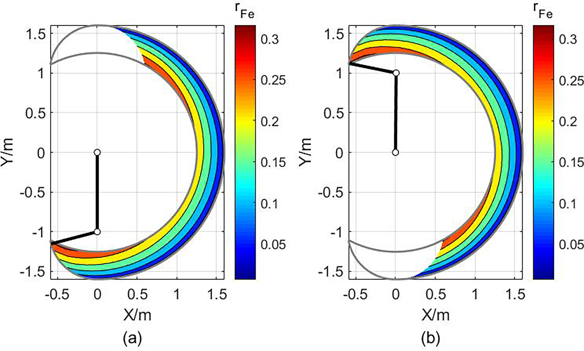
Figure 18 shows the comparison of the force manipulability ellipsoids and polytopes in the operating posture

End-effector force manipulability ellipsoids (a) and polytopes (b) for the posture

Force manipulability ellipsoids and polytopes of different operating postures of three given working points.

Comparison of the directional uniformity measures of force manipulability polytopes of different workspace discretization methods.
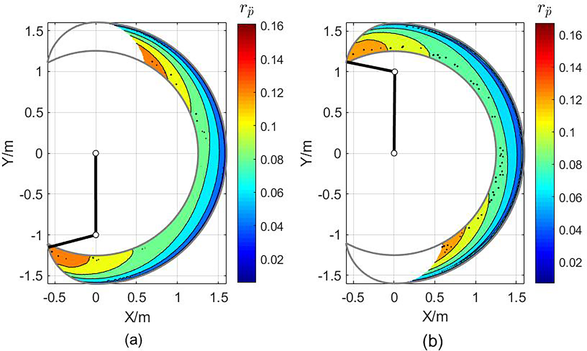
Figure 21 shows the end-effector acceleration manipulability ellipsoids and the polytopes in the operating posture

End-effector acceleration manipulability ellipsoids (a) and polytopes (b) for the posture

Acceleration manipulability ellipsoids and polytopes of different operating postures of three given working points.

Comparison of the directional uniformity measures of acceleration manipulability polytopes of different workspace discretization methods.
Conclusions
This article introduces a general method for the manipulability analysis of serial robot manipulator based on the construction of the feasible region of the manipulator constraints. Manipulator performance is quantified and characterized in terms of end-effector velocity, force, and acceleration manipulability polytopes. On the one hand, some typical difficulties such as nonlinear constraints, asymmetric joint constraints, redundancy of the manipulator, singularity of Jacobian, and singular configuration are considered and handled in our proposed method. On the other hand, the effects of the gravity, joint velocity and acceleration, and the payload on the end-effector manipulability are also taken into account in the evaluating process. Hence, our proposed method is universal for the analysis of the kinematic, mechanical, and dynamic manipulability of both redundant and nonredundant serial manipulators. Moreover, based on our proposed general performance analysis method, an overall architecture and corresponding procedures applicable to manipulability assessment for any given posture, practical or simulated end-effector operating trajectories, and entire workspace of a robot manipulator are established. The correctness and effectiveness of our proposed methodology are demonstrated by two practical applications, respectively, for two- and three-DOF planar manipulators. Further studies may include extending our method to robot mechanism design and motion planning and optimal control for optimal manipulability.