
Abstract
Introduction
Recently, palletizing robots have been widely used in the feed processing, food processing, and others palletizing cases to increase the efficiency and lower the costs. In the palletizing plants, the product sizes are a continuing diversification and the loading patterns vary greatly. In practical industrial applications, there are two main categories of robotic programming methods to generate the loading patterns. The first involved an online operation for the robot, using a teach pendent to input the motion command lines one by one. This is very cumbersome and time consuming. Moreover, the teaching involves trial and error that greatly affects the accuracy of the teaching points. The second is an off-line programming (OLP) that generates task data using a computer and downloads them to the robot controller. The OLP systems are widely used to reduce idle time of the robots and improve the production efficiency. 1 –3 Currently, various commercial off-line robot programming systems are available, such as RobCAD 9.0 and Delmia V5. 4 These commercial systems provide general functions for OLP, but these systems can’t be used in the typical palletizing robot, that is, a four-degree-of-freedom spatial parallelogram linkage. 5 Some dedicated OLP systems for palletizing robot, such as RobotStudio Palletizing Power Pac 6.03 6 and KUKA.PalletTech, are developed by the robot company, but these systems neglect the user requirement and can’t provide user-defined pattern. For the practical use of the proposed palletizing pattern generation system, a user-defined pattern should be in this system, and the user pattern can be stored in its own pattern. A graphic environment was developed to allow the user to configure the pattern, 7 but it’s too simple to meet the complex pattern.
In this article, we introduce a dedicated OLP system for palletizing robot and describe the major algorithms developed for the system. This system allows user to define patterns to generate the motion program, which can meet the user special requirements.
System design
OLP system for palletizing robot consists of pattern generation, motion planning, simulation, and motion program generation, as shown in Figure 1. Pattern generation combines the user-defined pattern and G5 heuristic to automatically generate the palletizing pattern. G5 heuristic finds the optimal solution of pallet loading problem that maximizes the number of boxes placed on a rectangular pallet. 8 In order to meet the practical demands, user defines the patterns with XML format stored in files. The pattern generation decodes the user-defined pattern file, checks overlapped area to achieve region for the upper layer, and generates pallet patterns. Motion planning finds collision-free paths between the gripping point and the place-down point in the configuration space to palletize the productions. Simulator calculates the velocity and acceleration of gripper to simulate the user-defined motion. Once the simulation is passed, motion program generation is carried out. Code for robot motion, process data, and so on is integrated into a complete robot program.

System structure.
Pattern generation
There are three methods to generate patterns. The first method involved an online generation using a teach-pendent to generate them or predetermined pattern. The second method is an off-line method that generates patterns using user-defined product topology and data. The last method is an optimized pallet pattern generation algorithm G5 heuristic to generate a loading pattern. We focus on off-line patterns generation using user-defined product topology and data. The patterns generation module decodes the user-defined patterns stored in the XML files, checks feasible patterns by the algorithm of the overlapped area, merges the surface of the current layer into the valid region for the upper layer by the algorithm of the region generation, and finally generates the user patterns.
User-defined patterns
The pattern is consisted of pallet data, production data, properties, and layer data, as shown in Figure 2. The pallet data includes length, width, and height. The production data is comprised of length, width, height, and weight of boxes or products. The pattern properties are consisted of layer number, the odd and even layers. The layer data describes the position of productions in pallet and the topology of productions in pallet. The user-defined patterns stored in XML files, which can meet many customer demands. The XML file format is shown in Figure 3.

The pallet pattern data.

XML file format.
Algorithm for overlapped area check
Pallet patterns determine the layout that loads small items (i.e. boxes or products) onto a large rectangle objects (i.e. pallet or container) without overlapping. This can be interpreted as geometric assignment problems, in which three-dimensional (3-D) small items have to pack into rectangular large objects. If the user-defined patterns are feasible, they are not overlapped at the same layer. Figure 4 shows the infeasible pattern due to the overlapped area. We proposed an algorithm to find whether the products were overlapped.

Overlapped area cases. (a) case 1 and (b) case 2.
Let A = {


Proposition 1
If rectangles A and B have overlapping area, there are
This proposition can be used to determine whether the products are overlapping. The algorithm is used recursively to estimate the overlapping of the products in the same layer.
Algorithm for region generation
The upper layer products must place on the current layer products. So the valid region of the current layer should be calculated. Polygon merging algorithm can be used to calculate the valid regions. The polygon merging algorithm can be described how to merge the adjacent rectangles into a polygon. That is how to merge a rectangle into a polygon. This article adopts the algorithm described in the study by Zalik. 9
Motion planning
Palletizing robot
The palletizing robot is shown in Figure 5, which is a four-degree-of-freedom spatial parallelogram linkage. There are two rotational and two transitional movements. The wrist represents the rotation of the entire manipulator around the rotational axis at the base. The other is the gripper’s rotation around its own axis. The first transitional movement represents the gripper’s up and down along the vertical lines. The other is the gripper’s forward and backward in the horizontal plane.

Palletizer robot schematic structure. 10
In most cases, palletizing robot repeatedly picks up the product from the conveyor belt and places it to the stacking pallet. The motion planning problem for palletizing robots is typically formulated as follows: gives a robot and a description of task and plans path of the robot between the conveyor belts to the stacking pallet. The path is collision free and satisfies certain requirements on motion accuracy and efficiency. Traditionally, there are two approaches to solve the problem: off-line planning and online planning. In this article, we consider the off-line motion planning. The palletizing robot plans the motion by taking into account the position and orientation of pallet, obstacles, and the kinematics constraints.
Obstacle
If there is an obstacle, it is surrounded by the smallest enclosing cuboid whose length, width, and height (LWH) are

Obstacle.
The angles at vertex
If

where

The minimum distance
Operation cycle
The palletizing order should be planned in the system and planned in the same layer. There are two rules to plan the palletizing order.
The two rules guarantee the palletizing order. The product is stacked from far to near.
One typical operation cycle is shown in Figure 7. The operation cycle can be divided into six steps.

Operational cycle.
Path planning
The palletizing operation cycle is divided into six steps. In order to guarantee safety, steps 1, 3, 4, and 6 need
Obstacles
In

XOY view.
If the following constraints are met, there is obstacle

where


When the projection of the obstacle in the XOY plane lies in the interior of the circle of radius
If there is obstacle, lift the production to height

Non-obstacle
If the equation(6) is not met, there is non-obstacle. The trajectory planning is similar to that of obstacle. The difference is that non-obstacle trajectory planning does not lift the products
Simulation and experiment
Development of 3-D robot simulator
We implemented the 3-D robot simulator based on the dimensional data of our real target machine, the CBT90, which is a four-axis industrial robot of Beijing CBT-BOT Technology Co., Ltd, China. This robot model is realized by a commercial CAD solidworks 2013, and the Graphical user interface is developed, using OpenGL 2.0 and QT4.7. The simulator is composed of simulation, pallet pattern generation, and path planning.
Pallet pattern generation
The user-defined pattern is shown in Figure 9. The production LWH is 500 mm, 300 mm, and 250 mm. The pallet LWH is 1300 mm, 1100 mm, and 750 mm. Odd and even layers are different. The layer number is 3. The pattern XML file is shown in Figure 3. The system reads the XML file, analyses the XML file to get the production information in each layer, checks the overlapped area to determine whether the pattern is reasonable in each layer, generates the valid region for each layer to determine whether the pattern is feasible in the upper layer, and finally generates the pallet pattern, as shown in Figure 9(a). Figure 9(b) and (c) shows the odd and even layers pattern, respectively. The centers of the adjacent production are connected by blue lines. The green dotted region is the valid region for upper layer.

The pattern generation. Grey box: production, Blue line: connecting the centers of the adjacent production, Green region: the valid region after merged. (a) Production information, (b) odd layer pallet pattern, and (c) even layer pallet pattern.
Simulation
According to the pattern XML file and the environment, the system plans the path to generate the end-effector motion. We simulate two cases: obstacle and non-obstacle. The coordinates of pallet vertex are (500 mm, 500 mm, and 200 mm), (500 mm, 1600 mm, and 200 mm), (1800 mm, 500 mm, and 200 mm), and (1800 mm, 1600 mm, and 200 mm), respectively. The coordinates of the obstacle vertex are (500mm, 0mm, 600mm), (500 mm, 700 mm, and 600 mm), (1500 mm, 500 mm, 600 mm), and (1500 mm, 700 mm, 600 mm), respectively. The coordinate of the grip point is (1000 mm, −1000 mm, and 125 mm). Figure 10 shows the simulation that there is no obstacle. The robot grips the production at the grip point, lifts the production to the preparing grip point, moves to the preparing place point, and finally puts down to the pallet. Figure 11 shows the simulation that there is obstacle. Unlike the Figure 10, the robot lifts the production to the safe height, so that it does not collide with the obstacle.

Non-obstacle simulations.
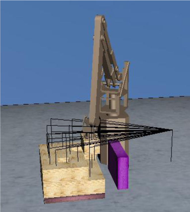
Obstacle simulations.
Experiment
Robot programs for handling liquor was effectively generated using the developed OLP software. The generated robot programs were optimized such that joint limits were avoided during the handling process. A major user interface for robot OLP as well as an example of the robot is shown in Figures 9 and 10. The generated programs were further downloaded into the CBT-BOT 90 robot controller to perform the handling tasks. From the experiments, it was observed that the position errors of robotic handling were ±0.5 mm, which is acceptable for the liquor handling. The pallet pattern was of the liquor put by the experimental palletizer robot was good, see Figure 12.

The robot handling liquor.
Conclusions
The strategy for user-defined pattern generation for palletizing robot is suggested. In the suggested method, as a means to generate the palletizing robot pattern, the generation pattern reads the user-defined pattern files, checks overlapped area, achieves region for the upper layer, and generates pallet patterns. Through the simulations and experiment method, the feasibility of the proposed method is investigated and confirmed that it is effective in the user-defined pattern generation.