
Abstract
Introduction
Mobile robots for land operation are required to travel on harsh and uneven environments. Some examples of their applications include search and rescue missions in military, industrial and nuclear accident situations, 1 –5 and also exploration missions on extraterrestrial planets. 6 –8 Needless to say, mobile robots should have high mobility to overcome highly uneven terrain conditions and obstacles.
Many researchers have tried to design and devise various types of driving mechanisms of mobile robots. The driving mechanisms can classically be categorized into three types. One is leg-type robot, which can cope with wide varieties of land conditions. However, it needs relatively complex hardware for leg structure and complicated control scheme to maintain the stability of the body. Also, its operation speed is rather slow and has low energy efficiency. 9,10 The second is a track-type robot, which has high mobility, but it has huge friction loss, especially when it changes the direction, and thus the energy efficiency is very poor. 11 The third one is wheel-type robot like the conventional automobile. It has most simple hardware structure, is fast, and the energy efficiency is good. However, its mobility is not satisfactory enough to confront various obstacles. 10,12
Beside the above-mentioned three types, another advanced type called hybrid-type robot has been developed by many researchers for better mobility. The hybrid type includes a combination of leg and track 13 or leg and wheel, 14 which has good mobility, but the structure is complex, needing complicated control scheme. One special case among hybrid types is the combination of passive linkage mechanism and wheel. Passive linkage mechanism, which replaces actively controlled legs and thus removes the problem of complex control algorithm, is aimed to enhance mobility. Also thanks to the use of driving wheel (instead of track), enabling it to run fast enough. A lot of this type of mobile robots have been proposed and their performances have been verified experimentally. 4,6,7,11,15
Even though many different types of mobile robots with the ability to travel on rough land conditions have been suggested, it is not easy to determine which one is better than the others. Thus, many studies on mobility evaluation were proposed. Thueer suggested a powerful metric for mobility evaluation. The author focused on a hybrid-type robot with passive linkage system and verified the suggested metrics by simulations. 15 –18 According to the authors’ results, a dominant factor in determining the robot’s mobility is its hardware structure, and the mobility cannot be improved when the hardware structure of the driving mechanism is fixed and thus is not transformable while traveling.
Other issues on mobility are energy efficiency and the capability to overcome obstacles. Even when a mobile robot is traveling over the same geometric terrain configuration and with the same running acceleration profile, the energy consumption may be different from one robot to another. Therefore, it would be better for a mobile robot to have high energy efficiency under fixed energy source (usually a battery). A mobile robot is apt to confront with step-like obstacles and thus the capability to overcome obstacles is another important issue for mobility.
In the Mobility evaluation section, three aspects of mobility, namely, stability, energy efficiency, and obstacle issue, are addressed. The studies discussed in Mobility evaluation section have found major factors influencing mobility, front and rear bogie link length and wheel size, and also explain the relationships. Based on the observation in Mobility evaluation section, a transformable mobile robot with changeable link length and wheel size is proposed to enhance the mobility as discussed in Design of a transformable mobile robot section. Simulation results comparing the performances of the proposed mobile robot with three conventional passive bogie-type robots are discussed in Simulation section.
Mobility evaluation
Several researchers with various points of view studied the mobility of field robots. For example, Apostolopoulos defines three terms of mobility. 19 One of them is “terrainability,” an ability of locomotion to negotiate rough terrain features without compromising the vehicle’s stability and going forward. In other words, the robot should remain stable and go forward when it passes the terrain. Mobile robots are generally operated as unmanned ground vehicle (UGV) or by teleoperation. It means that the user or engineer cannot manage when the robot falls into emergency situations such as rollover or stop due to discharge. For this reason, the robot should maintain its stability while operating on various kinds of terrains and the energy efficiency should be good enough. Therefore, it is reasonable to evaluate the mobility of a robot based on its stability, the energy consuming efficiency, and the ability to overcome obstacles while traveling.
Stability—stability margin
Stability measure of a mobile robot determines whether the robot can travel stably or it is rolled over and thus cannot move any further. When a mobile robot travels at relatively low speeds (which is usually the case), a quasi-static model to evaluate the stability makes sense with quite good precision since the effect of inertia on the stability can be reasonably neglected at low speeds. This makes it possible to derive stability criteria with little computational burden, which leads to its online computational implementation while a robot is traveling. Papadopoulos and Rey 20 in 1996 suggested a force–angle stability measure, which is simple and powerful since it uses the relationships between the mass center and the contact points between the vehicle and the ground. The authors’ method is briefly addressed below.
This method uses the tip-over angle to derive the stability margin. Figure 1 explains how the stability margin is geometrically obtained. The wheel–ground contact points are defined as


For each tip-over axis normal vector, the tip-over angle

The stability margin

Equation (1) is the measure of the stability margin and its unit is degree. Positive value of equation (1) means that the robot can travel stably. When it becomes “zero”, the robot is on the verge of rollover. Thus, a mobile robot on rough terrain should try to maintain the value
According to the above-mentioned stability measure, the criteria determining stable operation or rollover are dependent on the hardware structure of the robot body, especially the driving mechanism (which is usually fixed and not transformable) and the slope of the terrain where the robot is presently in contact with. This implies that when the robot is on the verge of stability, a slightly higher slope than the marginal one means the rollover of the robot. If a robot’s driving mechanism is transformable and is capable of appropriately changing the driving mechanism structure (e.g. the length of links and/or the wheel size), then the robot becomes able to overcome the marginally stable situation and to keep continuing the journey otherwise it fails to move further. Design of a transformable mobile robot section suggests the concept and mathematical approach of a transformable robot driving mechanism (in terms of link length and the wheel size). Simulation section shows the advantage and corresponding enhanced performances of a transformable robot compared with a conventional mobile robot in view of stability through simulations.
Energy consumption
Besides the stability issue, energy consumption is another critical issue on mobile robots, which are mostly UGVs, since such a robot is supposed to operate as long-time as possible under the limited energy source as in the study by Lachat et al. 22 Therefore, it would be greatly advantageous if a robot can efficiently consume the limited energy source throughout the operation. In this viewpoint, the amount of energy consumed by the wheels of a robot can be derived as

where
Design of a transformable mobile robot
Justifications for a transformable mobile robot design for mobility enhancement
Study on stability margin enhancement
In Mobility evaluation section, a measure of stability margin is described based on the kinematic approach. There are two dominant factors that determine the stability of the system: the location of center of mass (COM) and the location of the wheel–ground contact point (tip-over axis). Therefore, there are two ways to enhance the stability. One is to change the location of the wheel–ground contact point, and another way is to move the location of the COM. As in Figure 2, the stability margin is defined by the relationship between the wheel–ground contact point (tip-over axis in the figure) and the gravitational vector

Enhancing stability by changing the location of wheel–ground contact point. (a) Unstable case. (b) Stable case.
Figure 3 shows a schematic example of various locations of the COM depending on the link length and the wheel size changes. The body mass is selected to be 4 kg and the wheel mass 2 kg. The link length is changeable from 200 mm to 400 mm. The diameter of the wheel is changeable from 40 mm to 100 mm. The locations of the COM are varied depending on the link length and the wheel radius, which are depicted in Figure 3(b). The colored box in the left figure of Figure 4 shows various locations of COM, and the right colored column indicates the corresponding stability margin values. For example, when COM is located in the red area (bottom right) of the colored box of the left figure, the mobile robot has higher stability margin than the case of the blue area (top left). Therefore, for the same terrain configuration, there exists the length and the wheel size to achieve better stability margin.

Location of COM according to link length and wheel size change. (a) Design of four-wheeled mobile robot for stability analysis. (b) Movement of COM’s position by changing part dimension. COM: center of mass.

Stability margin value according to different locations of COM. COM: center of mass.
Study on torque consumption as energy efficiency
As addressed in Mobility evaluation section, the energy consumption can be indirectly evaluated from torque consumed during a certain period. If a robot can travel on uneven terrains with consumed torque minimized, the robot would travel longer in time and distance and will have high energy efficiency. The underlying idea is that the consumed torque might be dependent on the link length and the wheel size. In this section, we select a six-wheeled robot and analyze the relationships between consumed torque and link length and wheel size.
Figure 5 shows a free-body diagram of a six-wheeled robot on an uneven terrain. The figure describes a situation when two wheels (rear and mid-wheels) are on the same plane and the third wheel (front wheel) is on another plane. The consumed torque on each wheel can be derived as follows.

Free-body diagram to analyze the torque consumption of six-wheeled robot. (a) Dynamic terms. (b) Kinematic terms.
At

Therefore, a summation torque of all wheels is as follows

In the above equation,


Equation (4) verifies whether there are three factors to influence torque consumption. One is the multiplication of the moving acceleration of the mobile robot and the wheel size. This means that if the acceleration is high and/or the wheel size is bigger, the consumed torque becomes bigger, which is rather obvious. The second factor is the summation of the front and the rear link lengths. This length is determined by the distances between the front or rear wheel and the middle wheel. It means that if the front and rear wheels are located far from the middle wheel, the robot needs higher torque even with the same acceleration and the wheel size. And the third factor is the location of the COM from the rear wheel. The location of the COM is also determined by the front and the rear link length. Therefore, for the same motion of the robot, the torque consumption can be different depending on the wheel size and the link lengths. Therefore, if a robot has the capability of changing its link lengths and wheel size appropriately, the torque consumption can be reduced, which results in longer time and distance travel under constrained energy source.
Wheel size for obstacle overcome
As mentioned in the introduction, wheeled locomotion has several advantages over legged locomotion such as relatively simple structure, fast motion, and easiness for control. However, its drawback is the inability to cope with step-like obstacles. Figure 6 is a schematic diagram to analyze the working mechanism of a wheel and a step-like bump.

Free-body diagram to demonstrate relation between radius and height.
In this figure,


From these results, equation (8) gives the relationship between the applied force to lift the wheel over the obstacle and the wheel size and the obstacle height

Equation (8) tells that when the bump height approaches the wheel’s radius, the horizontal force to go over the bump should be increased nearly to infinity. In other words, if the bump height is higher than the wheel radius, the robot cannot go over the bump at all (if the friction effect between the wheel and the bump is taken into account, the maximum bump height would become less than this ideal case).
Suggestion for a transformable mobile robot design
It is understood that adjustable link length and wheel size will enhance the stability, energy efficiency, and obstacle overcome. This section suggests a design of a transformable robot that can adjust the link length and the wheel size while the robot is in the middle of traveling on uneven terrains. Figure 7 is the schematic diagram of the suggested robot. It is composed of six wheels and two passive (but horizontal length changeable) parallelogram bogies. The pair of two bogie structures has equally fixed link length of 100 mm and also has adjustable link length ranging between 0 mm and 150 mm. The wheel diameter is changeable from 40 mm to 100 mm. Figure 8 shows a prototype of the transformable mobile robot manufactured in our lab in order to experimentally verify the suggested ideas. It is also composed of six wheels and transformable links on bogie structure. The transformable mobile robot has several sensors: potentiometers for measuring angle between links and body in order to analyze the kinematics of the robot, incline sensor for checking the inclination of the robot body, and current measuring sensors for evaluating the energy efficiency. The body mass is 8.58 kg, each wheel part including motor is 0.60 kg, and suspension structures are 5.82 kg. The total mass is 18 kg.

Design idea of a transformable mobile robot.

Prototype manufactured a transformable mobile robot for experiments.
Figure 9 describes the details of the diameter-changeable wheel structure. It uses a scissor link mechanism to adjust the radius of the wheel. The scissor mechanism is wrapped with a rubber band as the surface of the wheel. Figure 10 shows a prototype of the transformable wheel manufactured in our lab. The diameter of the wheel is adjustable from 40 mm to 100 mm.

Design of transformable wheel. (a) Scissor mechanism. (b) Contraction. (c) Expansion.

Prototype of transformable wheel. (a) Contraction mode. (b) Expansion mode.
Figure 11 represents an example of a traveling scenario of this suggested transformable robot on an uneven terrain. As explained before, the stability margin and energy efficiency can be enhanced using adjustable link length and wheel size when it confronts with challenging surface configurations. Namely, the robot changes its link lengths and wheel sizes appropriately depending on the uphill or downhill situation such that the COM can be relocated so as to increase the stability margin. The energy efficiency also depends on the link length and the wheel size. In the next section, simulations to verify the mobility enhancement of the suggested robot are addressed.

A scenario of transformable robot operation on terrain.
Simulation
This section deals with the verifications of the proposed idea through various simulations by comparing its performances with those of conventional robots. Many different types of hybrid-type mobile robots having the combinations of passive links and wheels have been developed. 15 –18 Among them, this article selects three types, that is, Rocker-Bogie , RCL-E, and CRAB (especially, the RB-type robot is successfully employed in Mars exploration missions). The performances of these three-type robots are compared with those of the proposed transformable mobile robot. Figure 12 depicts the structures of three conventional types.

For fair comparisons in the simulation, the same dimensions for the robot body, link length, and wheel diameter are selected. For instance, the CRAB-type robot is symmetric in terms of front and rear configurations and thus going directions are not crucial compared with other two types.
As is commonly understood in the mobile robot–related literatures, the mobility is estimated by the stability, energy efficiency (which can be estimated by torque consumption), and the ability to confront with obstacles.
Figure 13 shows a schematic of the slope angle and six-wheel vehicle model for stability margin estimation. The dimensions of the main features of the robot are shown in Table 1, and the mass properties of the robot used in simulations are the same as those of the manufactured robot for experiments; body mass is 8.58 kg, wheel is 0.60 kg, and rest of all is 5.82 kg. The stability measure

Kinematic parameters for stability margin with slope.
Dimensions to get marginal slope of terrain (unit: millimeter).


An example of stability margin with respect to terrain slope.
Figure 15 shows a scenario of terrain configurations for simulations. “A zone” is a flat area. “B zone” consists of +20° uphill as stable area for conventional robots and +35° uphill where conventional robots would roll over due to the instability as discussed above. “C zone” is −35° unstable downhill. “D zone” consists of 15-mm step-type obstacle which is acceptable and 40-mm step-type obstacle which is not acceptable for robots with a fixed wheel diameter from 30 mm to 80 mm, respectively. But if the wheel diameter is over 80 mm, the robot could go over the 40-mm step. A feasibility of diameter-changeable wheel for obstacle climbing is going to be verified by simulations on Simulation for obstacle overcome capability section.

A scenario of terrain configuration for simulation.
Simulation for stability margin
Simulations for stability analysis are performed for the above-mentioned three typical mobile robots (RB, RCL-E, and CRAB) and the proposed transformable robot all with 100 mm of wheel diameters, traveling on the terrain as shown in Figure 15. Four cases of climbing uphill and the corresponding stability margin transitions are depicted in Figure 16. The figures tell that the stability margins of RB and CRAB robots go below zero when they reach +35° uphill region and thus cannot climb any further. On the other hand, the stability margins of RCL-E and the proposed robots are kept above zero and thus they can climb up the hill. This means that even though the mass properties, link dimensions (i.e. front and rear link lengths), and the wheel sizes are the same for the four types of robots, two types (RCL-E and transformable robot) are successful for climbing up and the other two (RB and CRAB) types fail to do so.

Results of ascending on B zone with 100 mm of wheel diameter. (a) RB. (b) RCL-E. (c) CRAB. (d) Transformable robot. (e) Stability margin on B zone. RB: Rocker-Bogie.
Figure 17 shows the four cases of going downhill of −35° through C zone. The stability margins of the three conventional nontransformable robots turn below zero and thus these robots fail to go down the hill. On the other hand, the proposed transformable robot is the only robot that can successfully descend the steep downhill.
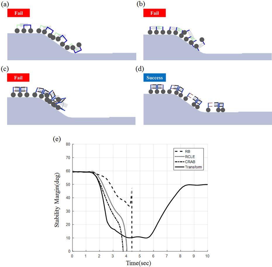
Results of descending on C zone with 100 mm of wheel diameter. (a) RB. (b) RCL-E. (c) CRAB. (d) Transformable robot. (e) Stability margin on B zone. RB: Rocker-Bogie.
In this simulation, the transformable robot uses the real-time information about the slope and changes its front and rear link lengths accordingly with moving range up to 150 mm so as to keep the stability margin above zero. As a result, the proposed robot is the only type that can accomplish the traveling successfully.
Simulation for energy consumption
As explained in Mobility evaluation and Design of a transformable mobile robot sections, the energy consumption can be indirectly estimated by the torque consumed, and the torque consumption depends on three factors: moving acceleration, the summation of front and real link length, and the location of the COM from the rear wheel. Figure 18 is an example of angular velocity and acceleration profile used in this simulation. From now on, we focus on five cases of the proposed robot traveling on the flat A zone with five different link and wheel dimensions as shown in Figure 19.

Acceleration profile for simulation of torque consumption.

Link and wheel size variations for simulation of torque consumption. (a) Case 1. (b) Case 2. (c) Case 3. (d) Case 4. (e) Case 5.
In Figure 19, case 1 through case 4 has 100 mm wheel diameters with different front and rear link lengths. Case 1 has the narrowest span between the front and rear wheels, and thus its COM is located nearest to the rear wheel center and the summation of the front and rear link lengths becomes the shortest among the five cases. On the contrary, case 2 has the widest span with both the longest front and rear links which makes its COM be located farthest from the rear wheel center. In cases 3 and 4, the summations of the front and rear link lengths are the same, but the locations of the COM from rear wheel center are different. Case 5 has the same shortest link dimension as case 1 but with smaller 40 mm wheel diameters, because the torque consumption also depends on the wheel size. Figure 20 shows the various results of the energy consumption for the five cases with the acceleration profile as shown in Figure 18.

Simulation results of torque consumption analysis. (a) Case 1 and case 2. (b) Case 3 and case 4. (c) Case 1 and case 5.
Figure 20(a) shows that narrower wheel span is advantageous over wider wheel span for energy consumption. Figure 20(b) tells that when the summation of the front and rear link lengths are the same, it would be helpful in terms of energy consumption if its COM is closer to the center of the rear wheel. Figure 20(c) means that smaller wheels consume much less torque compared with larger wheels. On the contrary, the conditions for stability are opposite to the conditions for energy consumption. Namely, for stability, it is better to have COM located far from the rear wheel center and to have the wheel span spread wider. This means that there exists trade-off between them and gives adequacy to suggest a transformable mobile robot for the mobility enhancement.
Simulation for obstacle overcome capability
As simple analysis in Design of a transformable mobile robot section shows, the capability to overcome step-type obstacles is majorly decided by the relative difference between the step height and the wheel size. In this section, the obstacle overcome simulation results are addressed. The four types of robots with the two cases of wheel diameters of 40 mm and 100 mm for two step heights of 15 mm and 40 mm as in D zone of the simulation terrain are simulated.
Figure 21 shows that the four robots with small 40 mm wheel diameter can successfully go over the low obstacle but cannot go over the high obstacle. Figure 22 shows that the four robots with large 100 mm wheel diameter can successfully go over both low and high obstacles. However, as discussed before, for the sake of torque consumption and stability, it is better to have small wheel diameter which is in conflict with the obstacle capability. Therefore, it is helpful to have diameter-changeable wheels, so that a robot travels with small wheel diameter to keep the torque consumption low and high stability margin. And yet when it confronts with high obstacle, the robot increases its wheel diameter adequately so as to go over the high obstacle.

Obstacle climbing simulation with 40 mm of wheel diameter. (a) RB. (b) RCL-E. (c) CRAB. (d) Transformable robot. RB: Rocker-Bogie.

Obstacle climbing simulation with 100 mm of wheel diameter. (a) RB. (b) RCL-E. (c) CRAB. (d) Transformable robot. RB: Rocker-Bogie.
Experimental results
This section addresses experimental results to verify enhanced mobility of the suggested transformable mobile robot by comparing the mobility of conventional linkage suspension robot. The CRAB-type robot has the same structure as the suggested link length changeable robot used in the experiment but with fixed link lengths. Thus, in these experiments, we use the CRAB-type robot as a conventional robot in order to compare its mobility in terms of stability and energy consumption with the suggested link length changeable robot. Furthermore, the mass properties and dimensions of the robot used in the experiment are the same as those used in the simulation.
Stability experiment
In the terrain conditions of the simulation, the critical uphill and downhill angle is 35°, and thus in order to verify rollover in the experiment, 36.8° slope (which is slightly larger than 35° to make sure) is used, which is shown in Figure 23. Figure 24 shows the snapshots of the stability experiment results. As shown in Figure 24, the CRAB cannot go up and down 36.8° slope. On the other hand, the suggested robot (with long span) can stably go up or down.

Stability experimental setup.

Snapshots of stability experiment results. (a) Transformable robot goes up 36.8° slope. (b) Conventional robot goes up 36.8° slope.
Figure 25 shows the corresponding stability margin values of the experiment. As expected in simulation results, the stability margin drops to zero for CRAB, and the stability margin of the suggested robot is kept over 10° in uphill and 20° in downhill and thus remains stable. The experimental results also confirm that the link length changeable robot has advantage over a conventional robot in terms of stability.
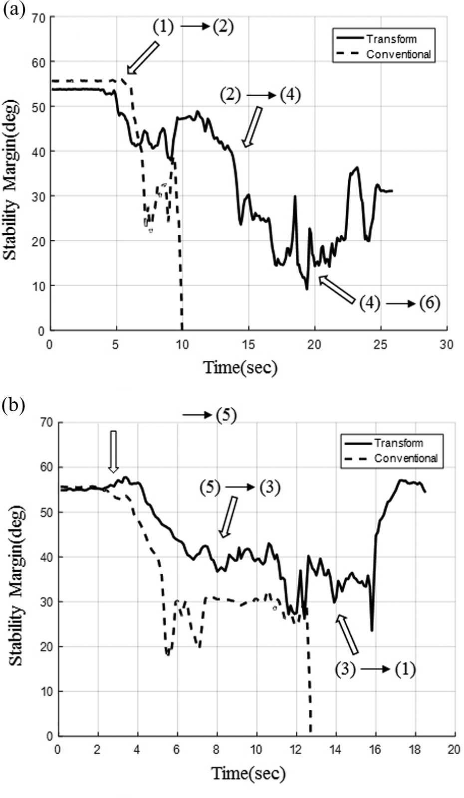
Stability margin values on stability experiments. (a) Stability margin on 36.8° up. (b) Stability margin on 36.8° down.
Energy efficiency experiment
In the energy efficiency experiment, the same four cases (cases 1–4) of the simulation in Figure 19 are performed as shown in Figure 26. For each case, the robot travels 30 m with similar acceleration profile. The consumed energy is calculated using the current meters implemented on each motor. Figure 27 shows the consumed energy in Joule for the four cases of Figure 19. As expected from the simulation, the amount of the consumed energy is highest in case 2, followed by case 4, and case 3, and is lowest in case 1. Therefore, this experiment verifies that in terms of the energy efficiency, the link length changeable robot is advantageous over a fixed link length robot.

Energy efficiency experimental setup and case conditions. (a) Experimental setup. (b) Case 1. (c) Case 2. (d) Case 3. (e) Case 4.

Energy efficiency experiment results.
Conclusion
In this article, the mobility is considered based on three aspects: the (static) stability, the energy efficiency estimated from the torque consumption, and the obstacle overcome capability. The measure of stability margin depends on the location of the COM and the front and the rear length of the bogie links. Namely, when a mobile robot is traveling uphill and downhill, it is better to have proper front and rear link length according to terrain conditions. Also, a small-size wheel is helpful to maintain the stability for both uphill and downhill traveling. In the view of energy efficiency, it is better to have a small span between the COM and the wheel contact point (i.e. shorter link length is helpful) and the wheel size to be small. On the other hand, larger wheel size is advantageous to overcome step-like obstacles. Based on these observations, we propose a transformable mobile robot with length-changeable link-type bogie and diameter-changeable wheel to enhance the mobility. The performances on stability, energy efficiency, and obstacle overcome capability are studied through simulations with three conventional bogie-type (with fixed link length and wheel size) mobile robots and the proposed transformable mobile robot. The simulation and experiment results show that if the link length and the wheel size of a mobile robot are adequately changeable while traveling on various terrain conditions, the robot can perform superior to the conventional-type mobile robots in terms of mobility.