This article studies the trajectory tracking control of underactuated underwater vehicles using control moment gyros through a biologically inspired approach based on homeomorphism transformation and Lyapunov functions in the horizontal plane. First, a series of assumptions and simplifications need to be made to build the kinematic and dynamic equations of the underwater vehicle under a single-frame pyramid configuration structured with four control moment gyros. Second, the error dynamics analysis of the submarine based on the control moment gyros is derived from the equations, and a tracking control algorithm is proposed to demonstrate the feasibility and stabilization of this tracking control scheme from theoretical analysis. Finally, the numerical simulation results are given for verifying the effectiveness and feasibility of the rendered control law.
There is no doubt that the development and protection of the ocean cannot be separated from research on marine engineering equipment. Study of underwater robots is an active field and may have a far-reaching impact on human beings.1 As one kind of important underwater robots, autonomous underwater vehicles (AUVs) should be able to be moved freely and manipulated conveniently. As internal control actuator devices, control moment gyros (CMGs) have been widely used in spacecraft and satellites.2,3 Despite their singularities and complicated nature, CMG systems can provide higher torque and large momentum to meet the typical requirements of the reactions of wheels.4 In particular, whether the speed of the vehicle is high or low, CMGs system can be appropriate for the attitude control, especially under zero momentum condition. In other words, the CMG-based underwater vehicle possesses a capability of zero-radius gyration under stationary state, so it can make a difference for maneuverability in narrow underwater space compared to the traditional underwater robots.5 Since Blair Thornton proposed Zero-G class AUVs using CMGs, a new class of research on AUVs that are able to accomplish attitude control unrestrictedly to some extent has been opened.5,6 Using CMGs as a new type of underwater actuator can be used to develop a novel control scheme, with a zero-turning-radius circle manipulated on the surface of a sphere based on the internal momentum exchange principle. However, the author did not consider the issue of trajectory tracking and formation control for AUVs using the CMGs.
As a fact and also implied by Brockett’s theorem (Brockett 1983),7 any smooth or continuous time-invariant feedback control does not make the solution of underactuated vehicle dynamics asymptotically stable, the stabilization of planar motion and tracking control has gradually become an active field.8 Unlike traditional underwater actuators such as thrusters, fins, and rudders, the CMG-based underwater vehicle can preserve the hydrodynamic integrity of its hull and be free of erosion or damage caused by harsh underwater environments or small creatures. Based on this, it makes the response speed independent of the interaction between fluid and its attitude control actuator. The above properties will make the CMG-based underwater vehicle possess wider application fields such as marine rescues, military scouting, and special operations. Recently, finite-time state feedback and output feedback for stabilization have been studied from different perspectives.9 Moreover, since homogeneity, σ-transformation and backstepping, and other methods have gradually been introduced in the study of the stabilization control problem, such as in observer-based backstepping control10,11 and neural networks,12–14 nonlinear model predictive control15 has begun to include state and input constraints, adaptive fuzzy logic systems,16 and sliding mode control.17–19 Sliding mode approach for path tracking of the unmanned agricultural tractor has been studied under restricted slipping effects and control saturation.20 In addition, the finite-time trajectory tracking of an autonomous surface vehicle21,22 has been achieved by adding a power integrator and a homogeneous-like controller in the research of Hong et al.,23 therein achieving finite-time tracking using the homogeneous theory. It should be noted that for the trajectory-tracking problem of mobile robot, in his study Sun24 utilizes a dynamic extension approach of the differential geometry control theory to fulfill the exact feedback linearization on the kinematic error equation. A distributed finite-time consensus tracking control for second-order multiagent systems has been developed based on a new class of observer-based control algorithms in the literature by He and Wang.25 In order to reinforce the control of inexact model, a kernel-based regression learning method is applied, in the literature by Lou and Guo,26 to estimate the inaccurate system parameters. In addition, incomplete symmetry underactuated USV tracking control27 has been developed using a cascade system. Unfortunately, most underactuated systems are developed using a sufficiently simplified model, and chatting phenomena may not be mitigated by the proposed control strategy.
Motivated by the above results, this article addresses a biologically inspired model used in the construction of a Lyapunov function approach for underactuated multidimensional systems, describing underwater vehicles using CMGs for trajectory tracking on the horizontal plane. Accordingly, this vehicle, containing a propulsion propeller coupled with CMGs system, should have the ability to control the three-axis attitude and move forward. Predictably, its underwater trajectory tracking is an interesting problem worthy to be discussed and studied. The control law involved in the design and analysis is based on backstepping, Lyapunov functions, and shunting neurodynamics models inspired by Hodgkin and Huxley’s membrane equation,28 therein using the biological neural system to replace the virtual control inputs to avoid differentiating the desired items. Nevertheless, it should be noted that the actual control strategies in the horizontal or vertical plane are not highly different.
The reminder of this article is organized as follows. In the “Preliminaries and problem formulation” section, we recall some assumptions on the models of the underactuated equation and use the homeomorphic transformation to modify the dynamical system. The “Trajectory tracking control law” section is devoted to designing a reasonable control scheme using the shunting model based on Lyapunov functions for this problem. In the “Simulation studies” section, the simulation results are presented to demonstrate the effectiveness and robustness of the proposed controller. Finally, conclusions and further considerations for the trajectory tracking control of this underwater vehicle using CMGs are provided in the “Conclusion” section.
Preliminaries and problem formulation
In this section, we consider the underwater vehicle using CMGs that is presented in Figure 1, where the square pyramid configuration is composed of the four-single gimbal control moment gyro (SGCMG) cluster and four CMGs located at the side-center position of a square pyramid, with gimbal axes perpendicular to the bottom face (Figure 2). It is important to note that Kurokawa studied the momentum envelope of the pyramid CMGs system by differential geometric theory and found that a third of its internal singular surface is passable.29 The kinematic and dynamic models of the underwater vehicle using the CMGs moving in the horizontal plane are presented, and a homeomorphic transformation is used to achieve a better control design and objective.
Small underwater vehicle using CMGs. CMG: control moment gyro.
Four-CMG cluster in a pyramid configuration. CMG: control moment gyro.
Through the Newton–Euler formulation and laws of conservation of linear and angular momentum, a dynamic model describing underactuated underwater vehicles using CMGs can be built. Decoupling the complex nonlinear system, coinciding with the kinematics, we can obtain the dynamical system in the horizontal plane
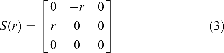
where and , and is the control input and R(ψ) is a rotation matrix given by
with the following properties: I, , and . Here,
Take P = [x, y]T as the vertical position in the inertial frame and ψ as the heading angle measured from the inertial axes. u, v, and r describe the surge, sway, and yaw velocities in the body-fixed frame, respectively; M and C(ν) are, respectively, the inertia matrix and the Coriolis and centripetal matrix (including the added mass); D(ν) is the drag matrix; and τdis is the disturbance vector. Notice that τ1 is the control input actuated by the propeller, and τ3 is the yaw moment provided by the CMGs. The following assumptions are made for the underwater vehicle to simplify the dynamical system and support the control scheme; in addition, some work must be performed beforehand to design the controller.
Assumption 1
The disturbance vector τdis is ignored, namely, τdis = 0.
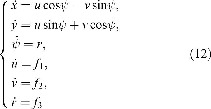
Then, the simplified dynamical system (equation (1)), based on the above assumption and studies,4,6 can be written as
where and , . Here, , , , , , , m is the mass of the vehicle, Iz is the moment of inertia about the yaw rotation, β = 54.73° denotes the pyramid skew angle,30h = 20 Nms is the magnitude of the angular momentum of each gyro rotor, and δ4 is the fourth CMG rotation angle about the axle h4 (see Figure 1).
Assumption 2
Similar to Behal et al. (2001)31, there exist bounded constraints, such as , , , , , and heading angle ψ ∈ [0, 2π], for the control inputs and velocities to ensure an effective control strategy. Here, , , , , and are positive constants.
Consider a desired sufficiently smooth trajectory path and the tracking errors , . In addition, define , where , and from the relationship between the inertial and body-fixed frames, there exists the following coordinate transformation
Use the properties above equation (3) to take the time derivative of equation (7) and considering the kinematical systems, we can obtain
Here, we have the following equivalence relations
Therefore, the tracking error vector under the inertial frame is equivalent to the error vector under the body-fixed frame . For the sake of designing a control scheme to make the vector become zero, similar to Pan et al.,13 an assumption about the desired path needs to be made.
Assumption 3
The desired path is sufficiently smooth, and its time derivatives are bounded.
For the complex system in equations (4) to (6), notice that the control inputs τ1 and τ3 are contained in the three equations. When considering the dynamical error analysis, this may cause numerous issues. Consider the following homeomorphic transformation
where , and the control inputs and the variation in the sway velocity are as follows:
where
For convenience and consistency, we use the previous notation. Then, the system equation (1) becomes
Trajectory tracking control law
To continue the following discussion, we shall investigate the model of shunting neural dynamics proposed by Hodgkin and Huxley28, which is recommended by Grossberg to understand real time adaptive behaviors and is applied in biological and machine vision, sensor motor control, and other areas.13,32,33 A typical shunting model can be written as
where ξi is the membrane potential of the ith neuron. The nonnegative constants A, B, and C represent the passive decay rate, and the variables and are called the excitatory input and the inhibitory input, respectively. This article combines the shunting model (13) with the backstepping method to design a reasonable control scheme for the new system (12).
Virtual controller design for the kinematics
The major change in the system equations (1) and (12) is that the control input τ3 is no longer in the differential equation concerning the sway velocity v, and the control objectives, namely, the surge and yaw velocities u and r, are tightly coupled with the sway velocity; therefore, the main goal is to converge the tracking error vector and φe to a small neighborhood of the origin.
First, consider the body-fixed tracking error vectors ex and ey, that is, making the actual path P track the desired path Pd; then, a positive-definite Lyapunov function is defined as
Consider equation (8) and obtain the time derivative
To make the Lyapunov function V1 be negative, set w = vp sinφe, and the virtual control inputs are assumed to be u and w. Then, the desired virtual control wd and are designed as follows:
where l1 and l2 are positive constants to be selected. Then, based on the shunting model equation (13), we obtain a new control wf to avoid differentiating wd
where A1 is a nonnegative constant and B1 and C1 are the upper and lower bounds of wf, respectively. The functions f(x) and g(x) are defined as f(x) = max{x, 0} and g(x) = max{−x, 0}. Then, we obtain new error variables δw and εw:
Substituting w = wd + (δw + εw) into equation (15) yields
Second, consider the orientation error φe and the virtual input error δw. Regard the yaw velocity r as a new virtual control input and take the time derivative of εw. We obtain
Then, we define the second Lyapunov function V2 as
Differentiating the function V2 yields
Introduce the virtual control yaw velocity r, and assume its desired control input as
becomes
Then, the virtual kinematical control inputs in (16) and in (22) are used in the following actual dynamical control scheme.
Virtual controller design for dynamics
Based on the virtual controllers u and r, the following section will discuss the actual control inputs τ1 and τ3 in the dynamics and will realize the design of the trajectory tracking control.
Similar to the control w using the shunting model (17), we obtain new controls uf and rf, and the shunting models are
The new error variables are
where the definitions of the constraints Ai, Bi, and Ci (i = 2, 3) are the same as in equation (17). Then, consider the errors above and substitute and into equations (15) and (21). The derivative of the function V2 becomes
Noting the dynamic equation (12) and differentiating the error variables in (25) yield
Finally, take the error variables εu and εr into account and define a new Lyapunov function as follows
where f1, f2, and Δ are defined in equation (11). Differentiating V3 with respect to time yields
where
and are also defined in equation (11). Then, the control inputs τ1 and τ3 are chosen as
where the parameters l4 and l5 are positive constants. Then, equation (29) can be rewritten as
Remark 1
If the proposed controllers in equation (31) and (32) are used in the transformed system (12), the trajectory tracking errors will convergent quickly to a small neighborhood of the origin, and its theoretical verification can be performed based on theorem 113; that is the coupled and transformed system can be tracked by the proposed control theoretically. As a main limitation, the resulting controller relies on the improved knowledge of the dynamical system.
Simulation studies
To demonstrate the effectiveness of the designed controller for the tracking control of underwater vehicles in the horizontal plane, simulation studies are conducted on the vehicle using the pyramid configuration CMGs, where the parameters are mainly from Yang et al.,34 as listed in Table 1.
Main parameters of the underwater vehicle.
m
31.4 kg
Iz
3.45 kg m2
−0.93 kg
−35.5 kg
1.93 kg m rad−2
1.93 kg m
−4.88 kg m2 rad−1
Xu|u|
−1.62 kg m−1
Xvr
35.5 kg rad−1
Xrr
−1.93 kg m rad−1
Yv|v|
−1310 kg m−1
Yr|r|
Yur
5.22 kg rad−1
Yuv
−28.6 kg m−1
Nv|v|
−3.18 kg
Nr|r|
−94 kg m2 rad−2
Nur
−2 kg m rad−1
Nuv
−24 kg
Our actual control objective is to track the desired trajectory [ηd, νd]T given by
where , the disturbance vector τdis = 0, and the initial conditions of the underwater vehicle are set as , , , and . Correspondingly, the controller parameters are chosen as l1 = 2.3, l2 = 1, l3 = 12, l4 = l5 = 0.01, A1 = A2 = A3 = 5, B1 = B2 = B3 = 6, and Ci = Bi, (i =1, 2, 3). Considering the actual error dynamics and the equivalent relation in equation (9), the error yaw angle ψe replaces φe in the simulation to avoid oscillations resulting from the inverse operation of the trigonometric functions. Then, from Figure 3, which plots the desired and actual trajectories, we can observe that the proposed control scheme is computationally efficient. The scheme also presents a high convergence rate and state performance in Figure 4, and in Figure 5 some oscillations appear in the initial stage. The actual system states η and ν and their desired targets ηd and νd are shown in the image, which shows that the designed controller achieves a good performance for the tracking control of positions and velocities simultaneously. The corresponding control force τ1 and torque τ3 are shown in Figure 6, which demonstrates that chattering is found in the control action. In addition, from the value of the torque input τ3, we can calculate the desired fourth angle δ4 of the gyro rotor; then, the actual control input can be realized.
Desired and actual trajectories in the xy plane within 20 s.
Desired and actual states x, y, and ψ.
Desired and actual states u, v, and r.
Control force τ1 and torque τ3.
Conclusion
In this article, a controller based on a biologically inspired model and Lyapunov functions acting on a transformed nominal underactuated system is proposed. The state of the underwater vehicle in the horizontal plane can be estimated by the designed state observer. Moreover, if the system is further modified or simplified, we can design a more intelligent learning algorithm using neural networks to achieve a better performance of the unknown or uncertain variables of the dynamics. It should also be noted that this control scheme can be transplanted in parallel to tracking for the vertical plane. In addition, this trajectory tracking control law is proposed to obtain the control signal of the thruster directly and the torque input to calculate the expected angle input of the fourth gyro rotor. The stability can be guaranteed by Lyapunov’s stability theory. Because of the fact that the virtual kinematic inputs are composed of the tracking guidance laws, and because the actual boundedness of the inputs is needed, the simulation results demonstrate reasonable robustness against parameter perturbation. Furthermore, if the trajectory tracking control for six--degree-of-freedom motion is considered, then more simplifications may be needed for the coupled non-affine nonlinear dynamical system, and other measures need to be taken to address both the unknown current or disturbance and the problem of how to design finite-time state feedback tracking controllers.
Footnotes
Declaration of conflicting interests
The author(s) declared no potential conflicts of interest with respect to the research,authorship,and/or publication of this article.
Funding
The author(s) disclosed receipt of the following financial support for the research,authorship,and/or publication of this article: This work was supported by the Natural Science Foundation of Hubei Province (no. 2013CFB154),the Open Foundation of the State Key Laboratory of Ocean Engineering,Shanghai Jiao Tong University (no. 1304),the Innovation Foundation of Maritime Defense Technologies Innovation Center,and the HUST Interdisciplinary Innovation Team Project.
References
1.
ShiLGuoSMaoS. Development of a lobster-inspired underwater microrobot. Int J Adv Robot Syst2013; 10(44): 1–15.
2.
The Bendix Corp. Control moment gyroscope gimbal actuator study. South Bend, IN: The Bendix Corp, 1966, p. 210.
3.
BranetsVNWeinbergDMVerestchaginVP. Development experience of the attitude control system using single-axis control moment gyros for long-term orbiting space stations. In: Proceedings of 38th congress international astronautical federation, Acta Astronautica, 1988, pp. 91–98.
4.
MonyAHablaniHB,SukumarS. Steering laws of single gimbal control moment gyros applied to spacecraft manoeuvres and tracking-a comparison. In: Control conference (ICC), 2016 Indiana, Hyderabad, India, 4–6 January 2016. DOI: 10.1109/INDIANCC.2016.7441144.
5.
ThorntonBUraTNoseY. Zero-G class underwater robots and unrestricted attitude control using control moment gyros. Oceans2007; 32(3): 1–5. DOI: 10.1109/OCEANSAP.2006.4393842.
6.
ThorntonBUraTNoseY. Internal actuation of underwater robots using control moment gyros. Oceans2005; 1: 591–598. DOI: 10.1109/OCEANSE.2005.1511781.
7.
BrockettRW. Asymptotic stability andfeedback stabilization. In: Differential geometry control theory. Boston: Birkhauser, 1983, pp. 181–208.
8.
YanZYuHZhangW. Globally finite-time stable tracking control of underactuated UUVs. Ocean Eng2015; 107: 132–146.
9.
AmatoFAriolaM,CosentinoC. Finite-time stabilization via dynamic output feedback. Automatica2006; 42(2): 337–342.
10.
SanthakumarM. Proportional-derivative observer-based backstepping control for an underwater manipulator. Math Prob Eng2011; 2011(4): 18.
11.
YangJYBaiDCWangSY. Trajectory tracking control of omnidirectional wheeled robot for lower limbs rehabilitative training. Robots2011; 33(3): 314–318.
12.
ZhangMJChuZZ. Adaptive sliding mode control based on local recurrent neural networks for underwater robot. Ocean Eng2012; 45(2): 56–62.
13.
PanCZLaiXZYangSX. A biologically inspired approach to tracking control of underactuated surface vessels subject to unknown dynamics. Exp Syst Appl2015; 42(4): 2153–2161.
14.
ZhuDQLiWCYanMZ. The path planning of AUV based on D-S information fusion map building and bio-inspired neural network in unknown dynamic environment. Int J Adv Robot Syst2014; 11(1): 1–14. DOI: 10.5772/56346.
15.
GuerreiroBJSilvestreC,CunhaR, et al. Trajectory tracking nonlinear model predictive control for autonomous surface craft. In: European control conference, Budapest, Hungary, 23–26 August 2009.
16.
NagAPatelSS,AkbarSA. Fuzzy logic based depth control of an autonomous underwater vehicle. In: Int Multi-Conf Autom, Kottayam, India, 22–23 March 2013, pp. 117–123.
17.
PezeshkiSGhiasiAR,BadamchizadehMA. Adaptive robust control of autonomous underwater vehicle. J Control Autom Elect Syst2016; 27(3): 250–262.
18.
HwangCLWuHM. Trajectory tracking of a mobile robot with frictions and uncertainties using hierarchical sliding-mode under-actuated control. IET Control Theory Appl2013; 7(7): 952–965.
19.
WangNQianCJSunJC. Adaptive robust finite-time trajectory tracking control of fully actuated marine surface vehicles. IEEE Trans Control Syst Technol24(4): 1454–1462. DOI: 10.1109/TCST.2015.2496585.
20.
MatveevASHoyMKatupitiyaJ. Nonlinear sliding mode control of an unmanned agricultural tractor in the presence of sliding and control saturation. Robot Auton Syst2013; 61(9): 973–987.
21.
AshrafiuonHMuskeKRMcninchLC. Sliding-mode tracking control of surface vessels. IEEE Trans Indus Elect2008; 55(11): 556–561.
22.
LvSLWangNLiangXL. Global finite-time trajectory tracking control of autonomous of autonomous surface vehicles. In: 12th World congress on intelligent control and automation (WCICA), Guilin, China, 12–15 June 2016, DOI: 10.1109/WCICA.2016.7578456.
23.
HongYGXuYS,JieH. Finite-time control for robot manipulators. Syst Control Lett2002; 46: 243–253.
24.
SunS. Designing approach on trajectory-tracking control of mobile robot. Robot Computer Int Manuf2005; 21(1): 81–85.
25.
HeXWangQ. Distributed finite-time consensus tracking control for second-order nonlinear multi-agent systems. In: Control Conf, Hangzhou, China, 28–30 July 2015, pp. 509–521.
26.
LouWGuoX. Adaptive trajectory tracking control using reinforcement learning for quadrotor J/OL. Int J Adv Robot Syst2016; 13(38): 1–10.
27.
WanLDongZPYue-MingLI. Trajectory tracking control of incomplete symmetry underactuated USV at high speed. Dianji Yu Kongzhi Xuebao Elect Mach Control2014; 18(10): 1–9.
28.
HodgkinALHuxleyAF. A quantitative description of membrane current and its application to conduction and excitation in nerve. J Physiol1952; 117: 500–554.
29.
KurokawaH. A Geometric study of single gimbal control moment gyros. Tokyo: University of Tokyo, 1998.
30.
WieB.Space vehicle dynamics and control, AIAA Education Series, ch. 11, 2008. American Institute of Aeronautics & Ast.
31.
BehalADawsonDXianB. Adaptive tracking control of underactuated surface vessels. In: Proceedings of the 2001 IEEE international conference on control applications, Mexico City, Mexico, 7–7 September 2001, pp. 645–650.
32.
YangSXMengM. Neural network approaches to dynamic collision-free trajectory generation. IEEE Trans Syst Man Cybern2001; 31(3): 302–318.
33.
YangSXZhuAYuanG. A bioinspired neurodynamics-based approach to tracking control of mobile robots. IEEE Trans Industr Elect2012; 59(8): 3211–3220.
34.
PresteroT. Verification of a six-degree of freedom simulation model for the REMUS autonomous underwater vehicle, REMUS (autonomous underwater vehicle). Master’s thesis, Massachusetts Institute of Technology and Woods Hole Oceanographic Institution, September2001. DOI: 10.1575/1912/3040.