
Abstract
Introduction
Integrating computational technology into a vehicle was not uncommon these days. The massive diffusion of computational embedded systems in the last decade had contributed to the creation of networks called Internet of Things. This technology concept already started to be implemented in the automotive sector. A premier example of this concept was the self-driving car or more commonly known as autonomous car technology, noticeably being developed by world’s largest and leading companies such as Uber, Google, and Tesla Motor. Currently, Tesla Motor dominates the autonomous car market in the world with its advanced Tesla Autopilot technology. 1 Tesla Autopilot enables the vehicle to be fully self-driven without requiring much human driver input, which means the car will drive by itself by relying on its advanced car sensors such as ultrasonic sensors, radar, and Tesla vision cameras controlled by the central processing unit installed on the vehicle. Tesla Autopilot managed to integrate its autopilot feature with collision prevention with the aim to improve its autonomous car safety. Besides, other car manufacturers also started to develop their own autonomous cars with the collision avoidance system.
The most popular types of collision avoidance systems were mostly relying on the sensors via camera, laser, and radar to detect the obstacles on the road and onboard computer system to navigate the vehicles. However, the technology suffered a setback when the first casualty caused by Tesla Autopilot was reported in the United States on May 7, 2016. 2 Preliminary investigation shows that the sensors and the camera system of the vehicles failed to detect a moving obstacle in front which caused the failure of the system to execute any collision avoidance maneuver such as emergency braking or evasion steering turns causing the accident. A better and comprehensive collision avoidance system requires a continuous improvement cycle to ensure autonomous car safety.
One of the promising solutions to improve the collision avoidance system is by integrating a two-way communication system between autonomous cars. The possibility of collision between autonomous cars and others is substantial with the lack of a two-way communication system or vehicle-to-vehicle (V2V) communication, together with the possibility of navigation-aided equipment error due to environment or external factors. By integrating the V2V communication technology into the current autonomous car, a better and safer collision prevention system or even an automated collision avoidance system can be developed. Autonomous cars will be able to obtain a detailed picture of the unfolding situations around them, revealing and preventing errors that even the sensor system alone would fail to detect and anticipate.
Current autonomous vehicles are solely dependent on sensors and cameras as input to maneuver and navigate the vehicle. Sensors and cameras used by the current autonomous vehicle as input for the navigation are proven to be not secure enough as both can be affected by weather and other external factors. Heavy rain can interfere with the sensors while snow or heavy fog will block the camera view, thus disrupt and cause the error to the image processing. Probability for an autonomous vehicle to involve in collision or accident with other vehicles is there when the sensors and cameras of the vehicle fail to detect other vehicles around it. With a two-way communication system, potential accidents can be mitigated since the vehicles will be able to estimate the other vehicles around them based on the current position, especially when the sensors and cameras fail to detect the obstacles.
In this research, the implementation of the V2V technology concept into the current autonomous car technology is investigated and researched. An algorithm for the collision avoidance system based on the combination of V2V technology and current autonomous car technology is developed in this work. The research will be carried via simulation and real-world experiments using TurtleBot. The objectives of the research will focus on: design and development of a collision prevention system by integrating two-way communication technology with current autonomous vehicle technology including sensors and cameras on mobile robots; development of an algorithm for the collision prevention system for multiple mobile robots; and testing of the collision prevention system algorithm and validating it using TurtleBot in Gazebo software simulation and real-world experiments, respectively.
The content of the article is organized as follows. The “Related work” section discusses the literature review that has been conducted for the collision avoidance algorithm of the autonomous car. The “Research methodology” section describes the approaches used throughout in this research work. The “Result and discussion” section presents a comprehensive analysis of the results obtained from the simulation and experiment conducted using the proposed algorithms. The “Conclusion” section finalizes the current work by providing recommendations for future work.
Related work
A comprehensive review focusing on the current autonomous technology, sensors used in autonomous vehicles, the V2V communication technology concept, and current collision avoidance algorithms available in Robot Operating System (ROS) is reported in this section.
Autonomous vehicles technology
An autonomous car is a self-driving car that takes over the human task to control a car and to relieve the driver from the task of driving. It enables elements within the transportation system to become intelligent by embedding them with smart sensing devices and empowering them to communicate with each other through wireless technologies.
According to the definition, intelligent transportation systems are those utilizing synergistic technologies and systems engineering concepts to develop and improve transportation systems from different aspects. 3 An autonomous car provides more convenience and, safety and less energy-intensive to the driver. Current autonomous cars such as Tesla Model 3 and Google Self-Driving Car provide the functionality of “fully self-driven,” meaning the car will drive by itself without requiring much driver input by relying on its advanced car sensor and computer vision camera. 4 Fully autonomous car developments are still in its pullulating stages. Currently, there are several research and development divisions of automobile companies such as Audi, Toyota, Ford, Volkswagen, Mercedes, BMW, Volvo, Tesla, and Google still developing their own autonomous car. The notion of realizing autonomous vehicles or self-driving cars can be achieved by designing an efficient advanced driver assistance system. 5
Sensors of autonomous vehicles
The convergence of sensor-based technologies is extensively used in autonomous vehicles. Sensor-based systems offer varying degrees of assistance to the driver. The fusion of available sensors and artificial intelligence is used to assist the autonomous system to understand the vehicle’s surroundings. The fundamental sensors normally used by autonomous vehicles are radar, light detection and ranging (LIDAR) or laser, camera, and so on. Radar is the most commonly used equipment in autonomous vehicles. It is mainly used for motion measurement by using radio waves to determine the velocity, range, and angle of objects. 6 Radar is computationally lighter than a camera and uses far lesser data than LIDAR. While less angularly accurate than LIDAR, radar is capable to work in every condition and can even use reflection to see behind obstacles. LIDAR is favorably used for 3D mapping. LIDAR is a technology that measures distance using laser light. The technology can scan more than 100 m in all directions (360° imaging), generating a precise 3D map of the car’s surroundings that are very vital for autonomous cars to make intelligent decisions. 7 The disadvantages of LIDAR are its high cost to manufacture and the large amount of data that it generates while in operation. Infrared cameras use infrared radiation to form an image. Infrared camera is popular for its capability to capture image or video under low light conditions. Infrared camera is used for autonomous car navigation assistance during night or dark situations. 8 Computer vision by far is the cheapest and most readily available sensor. Computer vision uses massive amounts of data during operation, creating millions of pixels or megabytes at every frame, thus making the processing computation intense and algorithmically complex. 9 The main advantages of computer vision are its capability to see real image and color, making it the best for scene interpretation, in comparison with LIDAR and radar.
V2V communication technology
Proposed V2V system or “two-way communication system” will enable each car on the road to “communicate” with each other and broadcast their position, speed, steering wheel position, brake status, and other related data to other vehicles within connection range by using dedicated short-range communication (DSRC) systems that are capable of transmitting information including positions in every 100 ms, 10 in accordance to Vehicle Safety Communications Consortium of Vehicle Infrastructure Integration requirement. 11 This system also enables cars to establish ad hoc networks to cooperate, by providing the information about traffic, allowing sensing and broadcasting of security warnings, such as accidents and road issues. DSRC system is another protocol for wireless communication different from Wi-Fi which is intended for wireless communication between vehicles. 12 The computers aboard each car process various readings being broadcasted by other vehicles multiple times for every second, each time calculating the chance of an impending collision. Transmitters use a dedicated portion of the wireless spectrum as well as a new wireless standard, 802.11p, 13 to authenticate each message.
Collision avoidance algorithms in ROS
The ROS is considered as a flexible framework for writing robotic application software. 14 ROS is an open-source toolkit with the aim to prevent robot developers to start from scratch when developing their own robot. ROS enables the programming code to be reused in robotics research and development that has been done by previous researchers. ROS provides many useful tools, hardware abstraction, and message-passing system between nodes. Nodes run independently and communicate with others via topics using one-to-many subscriber model and the TCP/IP protocol. Packages developed include features such as low-level driver for sensors, universal transport layer and ready-to-use implementation of the latest state-of-the-art algorithm for data fusion, 2D and 3D mapping, path planning, and autonomous driving system. 15 One example of the application of ROS in this research is the 3D mapping framework. 16 In this research, ROS will be used in programing and running the TurtleBot using available packages such as the navigation stack and mapping stack. Google Lightweight Communication and Marshalling (LCM) is a set of tools or libraries for information exchange and data marshaling for various programming languages. 17 There are several collision avoidance system packages available in the ROS library including optimal reciprocal collision avoidance system (ORCA), ClearPath algorithm, and multi-robot collision avoidance with localization uncertainty system (CALU).
ORCA was introduced by Van Den Berg et al. 18 Using the ORCA system, robot agents independently computed half-planes of collision-free velocities for each other agent. Each robot will take half of the responsibility of avoiding pairwise collision to ensure collision-free motion. This results in smoother motion of the robot when avoiding collision between them. ClearPath algorithms are developed and introduced by Guy et al. with the capability to efficiently compute collision-free velocities. 19 The algorithm is suitable for different variations of velocity obstacles (velocity obstacles, reciprocal velocity obstacles, or hybrid reciprocal velocity obstacles) used in ROS. ClearPath follows the concept that the collision-free velocity is defined as the closest to the preferred velocity on the intersection of two-line segments for any two-velocity obstacle, or the projection of the preferred velocity onto the closest leg for each velocity obstacle. Multi-robot CALU was introduced by Claes et al. 20 This system uses ORCA, and the combination with the extension of non-holonomic robots (NH-ORCA) and adaptive Monte Carlo localization (AMCL). This system computes collision avoidance action independently for each robot (decentralized system) based on sensors’ information and data exchange between each robot.
Research methodology
The methodology adopted for this work is explained in this section. To enable the simulation and experiment to be conducted, a meticulous combination of hardware and software is required. Figure 1 shows the block diagram of the system architecture that has been used in this research. Hardware used in this work include TurtleBot, Kinect sensor, Hokuyo laser range finder, Raspberry Pi/Laptop, and a Wi-Fi router. All of the hardware were assembled and connected to the TurtleBot. Most of the system connections are powered by the TurtleBot battery, except for the laptop computer.

Block diagram of the TurtleBot.
The algorithm was loaded into the Raspberry Pi/Laptop to program the TurtleBot for the autonomous navigation system. The Raspberry Pi/Laptop acts as the central processing unit of the systems connected to the TurtleBot responsible of running the navigation system and also the collision avoidance system. The laptop computer was connected to the Wi-Fi router wirelessly and acts as the secondary data input for TurtleBot navigation and movement system. The Wi-Fi router allows TurtleBot to communicate with another TurtleBot using Google LCM, which is similar to the DSRC system. This system enables the TurtleBot to exchange data with each other. Kinect sensors and Hokuyo laser range finders were acting as the primary data input to determine the navigation and movement of the TurtleBot. Kinect sensors consist of a color camera and depth camera that is capable of capturing image and recording video in color format, plus an infrared (IR) emitter and an IR depth sensor that can measure the distance between the object and the sensor via reflection of the IR light beams. For software, ROS in Python and C are used in this research. The setup was done to replicate the autonomous car set up with V2V communication. The research work started with developing the algorithm which was tested through simulation. Later, the developed algorithms were tested and validated through field experiments.
Proposed system algorithms
In this research, two main algorithms were developed namely collision avoidance system without inter-robot communication (CASA-1) and collision avoidance system with inter-robot communication (CASA-2). CASA-1 represents the current autonomous collision avoidance system (without peer-to-peer communication system) where only input from sensors is considered for its collision avoidance system. CASA-2 represents the proposed collision avoidance system algorithms with peer-to-peer communication where the input from sensors and also data exchanged between robots using inter-robot communication containing velocity and position are considered for its collision avoidance system.
During the inter-robot communication phase, each robot broadcasts its velocity and position information in the global coordinate frame on the common ROS topic through wireless networks and also subscribes to the same topic and caches velocity and position data of other robots. The robot positions were determined based on forwarding integrated in time according to the motion model of robots via the last known position and velocity information. The inter-robot communication system is based on the DSRC using Google LCM. Figure 2 shows the flowchart of the proposed collision avoidance system. Two main inputs were considered in this system, the sensors input and data from the LCM system for the collision avoidance system. The system ends when there is no possible collision occurrence and the TurtleBot reaches the navigation goal.

Flowchart of the proposed collision avoidance system.
Experimental setup
Two sets of TurtleBot were placed on a track with each connected with the Kinect sensor and Hokuyo placed on the TurtleBot facing front and placed in a line as shown in Figure 3. Wi-Fi router was placed on top of one of the TurtleBot that was connected to the central processing unit. Both of the TurtleBots were placed with a certain distance between each other. The initial position and distance of the TurtleBot are calculated using rear end collision scenario (RECS) setup and junction crossing intersection collision scenario (JCICS) setup. This setup was designed to replicate the distance of autonomous cars in real-world situations. Experimental setup is explained as below:
Both TurtleBot hardware connections are calibrated and ensure nodes are registered in ROS.
Both TurtleBot are configured and set up for RECS and JCICS, respectively.
Both TurtleBot are placed/set to the initial positions and the algorithms are uploaded to both TurtleBot for field testing.

Junction crossing intersection collision scenario.
Rear end collision scenario
Figure 4 shows the experimental setup of the research, namely RECS. For the simulation and experiment setup, equation (1) was used to determine the minimum distance needed between two TurtleBots 21

where

Rear end collision scenario.
Similarly, equation (2) can be used to find the minimum distance between two TurtleBots for the Lead vehicle stopped scenario 22

For this scenario, assuming 2 s of time before the collision with the default constant speed of 0.5 m/s for TurtleBot, the minimum distance required between two TurtleBots was determined to be 1 m. The distance was acceptable as a Kinect sensor is able to detect obstacles up to 3.5 m away.
The procedure of the experiments is explained below: TurtleBot-2 is set to move autonomously while Turtlebot-1 is set to move manually. Sensors of the autonomous TurtleBot-2 were set to detect TurtleBot-1 in front via sensors and wireless communications setup. TurtleBot-1 is moved manually via wireless control. TurtleBot-2 followed TurtleBot-1 autonomously with constant speed. TurtleBot-1 is instantaneously stopped manually. Response of TurtleBot-2 is observed and recorded. The experiment is repeated for 10 times.
Junction crossing intersection collision scenario
Figure 3 shows the experimental setup of the research, namely JCICS. For the JCICS, antipodal circle method 23 is used to calculate the distance required between two TurtleBots as shown in Figure 5.

where

Antipodal circle method to determine the distance required between TurtleBot 1 (T1) and TurtleBot 2 (T2).
The procedure of the experiments is shown below: TurtleBot-2 is set to move autonomously while TurtleBot-1 is moved manually. Sensors of the TurtleBot-2 were set to detect TurtleBot-1 in front of junction via sensors and wireless communications setup. TurtleBot-2 in front of the junction is moving autonomously with constant speed. TurtleBot-1 moves manually to intercept/cross paths with the TurtleBot-2 via manual control. Response of TurtleBot-2 is observed and recorded. The experiment is repeated 10 times.
Result and discussion
There are two results obtained in this work which are CASA-1 and CASA-2 being implemented on simulation and real-world experiment. This work also contains the information of finalized simulation and experiment setup with a detailed explanation, and also the RECS and JCICS simulation and experiment implementation.
Simulation and experimental setup
Using Gazebo simulation, straight and junction roads world were created, respectively, each with two TurtleBots included in the simulation world. The real environment was then mapped using
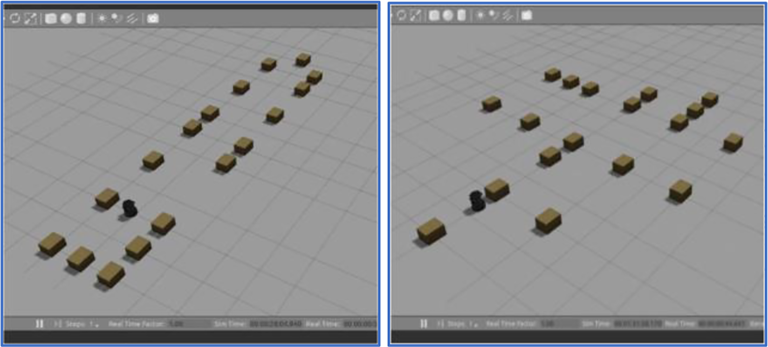
World simulation of straight road (left) and junction road (right).

Generated map file of the straight road (left) and junction road (right).

Experimental setup (left) and mapped image (right) of workspace.
Simulation and experiment implementation
Both simulation and real-world experiments were conducted separately in RECS and JCICS. By utilizing the created world and map, both simulation and real-world experiments were carried out by using two TurtleBots. For each scenario, four different conditions are tested which are Lead TurtleBot sudden stop (LTS), Lead TurtleBot decelerate (LTD), Lead TurtleBot slower speed (LTSS), and straight crossing path (SPD). Simulations and experiments were repeated 10 times for each condition.
RECS simulation and experiment
TurtleBot-1 and TurtleBot-2 were set and run for LTS, LTD, and LTSS conditions. Figure 9 shows the process of the simulation for the RECS simulation. TurtleBot-2 (Follower) was set to move autonomously toward another endpoint via navigation goals. TurtleBot-1 (Lead) was controlled manually and leads in front of the TurtleBot-2. TurtleBot-1 was manually stopped/decelerate after halfway of the track. TurtleBot-2 collision avoidance reactions were observed and recorded. Figure 10 shows the process of the real-world experiment. TurtleBot-2 (Follower) is set to move autonomously toward another endpoint via navigation goals. TurtleBot-1 (Lead) was controlled manually and leads in front of the TurtleBot-2. TurtleBot-1 was manually stopped/decelerate after halfway of the track. TurtleBot-2 collision avoidance reactions were observed and recorded.

Process of the simulation for rear end collision scenario.

Process of the real-world experiment for rear end collision scenario.
Junction road collision scenario simulation and experiment
TurtleBot-1 and TurtleBot-2 were set and run accordingly for junction crossing collision scenario. Figure 11 shows the process of the simulation for the junction crossing collision scenario. TurtleBot-2 was set to move autonomously toward an endpoint via navigation goals. Simultaneously, TurtleBot-1 was controlled manually toward TurtleBot-2 navigation path perpendicularly. TurtleBot-2 collision avoidance reactions were observed and recorded. Similarly, TurtleBot-1 and TurtleBot-2 were set and run accordingly for JCICS. Figure 12 shows the process of the real-world experiment for the JCICS. TurtleBot-2 was set to move autonomously toward another endpoint via navigation goals. TurtleBot-1 was controlled manually and leads toward TurtleBot-2 navigation path perpendicularly. TurtleBot-2 collision avoidance reactions were observed and recorded.

Process of the simulation for junction crossing collision scenario.

Process of the real-world experiment for junction crossing intersection collision scenario.
Simulation and experiment results with CASA-1 and CASA-2 algorithm
Rear end collision scenario
Based on the obtained simulation results in Table 1, it is shown that the success rate of collision avoidance running with the CASA-1 algorithm is 60%, 70%, and 80%, respectively, for LTS, LTD, and LTSS scenarios. It is shown that the LTS scenario has the lowest success rate since only 6 out of 10 trials are successful, followed by LTD and LTSS scenarios. Figure 13 shows the detailed simulation and experiment results for the RECS for LTS, LTD, and LTSS scenarios with CASA-1 algorithm. On average, the time required for the TurtleBot-2 to reach its navigation goals while evading collision is about 17.0 s for LTS scenario, 18.0 s for LTD scenario, and 17.0 s for LTSS scenario. Note that the average times include the times where collision evasion is unsuccessful, which usually caused longer time required for TurtleBot-2 to complete the navigation goals.
Success rate results for the rear end collision scenario with CASA-1 and CASA-2 algorithms.

CASA-1: collision avoidance system without inter-robot communication; CASA-2: collision avoidance system with inter-robot communication; LTS: Lead TurtleBot sudden stop; LTD: Lead TurtleBot decelerate; LTSS: Lead TurtleBot slower speed.

Graph of LTS, LTD, and LTSS scenarios for rear end collision using CASA-1 algorithm in simulation and experiment. LTS: Lead TurtleBot sudden stop; LTD: Lead TurtleBot decelerate; LTSS: Lead TurtleBot slower speed; CASA-1: collision avoidance system without inter-robot communication.
Experiment results in Table 1 show an increase in success rate compared with simulation results with 70%, 80%, and 80% success rates for LTS, LTD, and LTSS scenarios, respectively. LTD and LTSS have the same success rate compared with the simulation results. These differences might be due to human error or random condition such as the environmental conditions during the experiment. Overall, the results are acceptable and consistent with the simulation results. The average time required for the TurtleBot-2 to reach its navigation goals while evading collision is 17.0 s for LTS scenario, 17.4 s for LTD scenario, and 18.2 s for LTSS scenario.
Figure 14 shows the detailed simulation and experiment results for the rear end collision for LTS, LTD, and LTSS scenarios using CASA-2 algorithm. Based on the simulation results in Table 1, after integrating the velocity and position into the current system (CASA-2), a 100% success rate of collision avoidance was achieved for LTS, LTD, and LTSS scenarios. On average, the time required for the TurtleBot-2 to reach its navigation goals while evading collision is about 14.1 s for LTS scenario, 16.8 s for LTD scenario, and 15.6 s for LTSS scenario. Overall improvements in terms of time are shown in comparison with the average time of the same scenario (LTS, LTD, and LTSS) using CASA-1 algorithm which are 17.0, 18.0, and 17.0 s, respectively. Similarly, with the simulation results for RECS using the CASA-2 algorithm, a 100% success rate of collision avoidance was achieved in real-world experiments for LTS, LTD, and LTSS scenarios, as shown in Table 1. On average, the time required for the TurtleBot-2 to reach its navigation goals while evading collision is about 15.0 s for LTS scenario, 17.0 s for LTD scenario, and 15.7 s for LTSS scenario. Overall, the experiment results are consistent with the simulation results with CASA-2 algorithm.

Graph of LTS, LTD, and LTSS scenarios for rear end collision using CASA-1 algorithm in simulation and experiment. LTS: Lead TurtleBot sudden stop; LTD: Lead TurtleBot decelerate; LTSS: Lead TurtleBot slower speed; CASA-2: collision avoidance system with inter-robot communication.
Junction crossing intersection collision scenario
From the simulation results obtained (Table 2), it is shown that the success rate of collision avoidance for junction crossing intersection is just merely 60% with 6 successful attempts out of 10. This may be due to Kinect sensor’s limitation on horizontal viewing angle (70°), thus unable to detect TurtleBot-1 that approaching from perpendicular direction. Figure 15 shows the detailed simulation and experiment results for the junction crossing intersection collision for SPD with the CASA-1 algorithm. The average time required for the TurtleBot-2 to complete its navigation for the SPD scenario is around 21.0 s. The success rate of collision avoidance via experiment was increased by 10%, as shown in Table 2, if compared with the simulation results for the same scenario. The experiment results were consistent with the simulation results. For the SPD scenario, the average time for the TurtleBot to complete its navigation goals is around 19.0 s, 3.0 s shorter compared to the simulation time. Note that the average times are calculated that includes the times where collision evasion is unsuccessful, which usually caused more time needed for the TurtleBot to fully complete its navigation goals.
Success rate results for junction crossing intersection collision scenario with CASA-1 and CASA-2 algorithms.

CASA-1: collision avoidance system without inter-robot communication; CASA-2: collision avoidance system with inter-robot communication; SPD: straight crossing path.

Graph of SPD scenario for junction crossing intersection collision using CASA-1 algorithm in simulation and experiment. SPD: straight crossing path; CASA-1: collision avoidance system without inter-robot communication.
Figure 16 shows the detailed simulation and experimental results for the junction crossing intersection collision for SPD with the CASA-2 algorithm. In simulation, a 100% collision avoidance success rate is achieved via virtual simulation when using the CASA-2 algorithm. Table 2 shows the simulation results for the JCICS. In this SPD scenario, the average time needed for the TurtleBot to complete its navigation goals is merely 14.0 s. This is due to the smoothness of the navigation, where there is no collision and jerky movement when traveling toward the navigation goals. The experiment shows a 100% collision avoidance success rate when using the CASA-2 algorithm. Table 2 shows the real-world experiment results for the JCICS when running with the CASA-2 algorithm. For the SPD scenario, by using the CASA-2 algorithm, the average time needed for the TurtleBot to complete its navigation goals is around 13.7 s, slightly shorter in terms of time compared with the average time of simulation with 14.0 s. The results consist of the simulation and are accepted. The shorter time required for TurtleBot-2 to complete the experiment may be due to the better navigation system provided by the CASA-2 algorithm.

Graph of SPD scenario for junction crossing intersection collision using CASA-2 algorithm in simulation and experiment. SPD: straight crossing path; CASA-2: collision avoidance system with inter-robot communication.
Discussion
There are several failure cases, problems, and limitations encountered during the testing mainly involving TurtleBot localization method, limitation of TurtleBot itself in simulating as an autonomous car, and the recalibration of the TurtleBot needed after a few runs of the experiment.
Trajectory data
Figures 17 and 18 show the trajectory data example of TurtleBot during the collision avoidance maneuver using the CASA-1 algorithm. The trajectory data are obtained by using Rviz in real time during the simulation and experiment. The figure on the left shows the trajectory path continues with a smooth gradient indicating a successful collision avoidance maneuver is achieved by TurtleBot. Figures on the right show the failed collision avoidance where the trajectory path seems to be stuck and “looping,” indicating that collision has occurred. For this condition, TurtleBot is stuck and entered into recovery mode by turning in a circular motion to scan the surrounding. Hence, TurtleBot will be able to find alternative routes before continuing its path toward the navigations goals.

Success (left) and failure (right) trajectory data for rear end collision scenario with CASA-1 algorithm. CASA-1: collision avoidance system without inter-robot communication.

Success (left) and failure (right) trajectory data for junction crossing intersection collision scenario with CASA-1 algorithm. CASA-1: collision avoidance system without inter-robot communication.
Figure 19 shows the trajectory data example of TurtleBot during the collision avoidance maneuver using the CASA-2 algorithm. Using the CASA-2 algorithm, both TurtleBots will able to communicate and exchange data (velocity and position) through the LCM system. Then, TurtleBot-2 is able to prevent the collision with TurtleBot-1 while navigating to its own goals in both road scenarios (RECS and JCICS). The trajectory data of TurtleBots are obtained by using Rviz in real time during the simulation and experiment, which means both are connected wirelessly via the LCM system.

Trajectory data for rear end collision scenario (left) and junction crossing intersection collision scenario (right) with CASA-2 algorithm. CASA-2: collision avoidance system with inter-robot communication.
Localization problem using AMCL
TurtleBot defines its location based on the AMCL method rather than GPS for an autonomous vehicle. Monte Carlo localization, also known as particle filter localization, is a widely applied localization method in the field of mobile robotics. The algorithm estimates the position of a robot as it moves and senses the environment. For TurtleBot, it uses its sensor’s readings to estimate its location relative to its starting position. Due to this reason, a false localization problem or a Kidnapped robot scenario commonly occurs if there are several locations that are represented similarly according to the sensor values. For example, in straight road collision scenario simulation world setup, a long hallway in which both ends are almost the same. As a result, TurtleBot sometimes will localize itself in the wrong position. To reduce this error in the work, boxes are arranged differently in sequence in the simulation world while two markers (a box and a table) are used in a real-world experiment.
TurtleBot limitation in representing actual autonomous vehicles
Due to TurtleBot’s non-holonomic drive characteristic and only use two wheels rather than four wheels for normal autonomous cars, collision scenario data of TurtleBot in this work might not be able to fully represent the actual collision scenario of the four wheels autonomous car. Besides that, TurtleBot’s relatively low maximum speed limit (0.7 m/s) and its sensors’ ability to detect obstacles up to 5 m mean that TurtleBot has a higher probability to evade collision since it got longer time to detect and avoid collision. Hence, it might influence the overall results. Both aspects are considered as the research limitation.
Frequent recalibration of TurtleBot positioning in a real-world experiment
Other than that, the TurtleBot position needs to be recalibrated for each 5–7 runs in the real-world experiment. This may be due to the wheel slip since the surface of the experiment location is made out of tile. However, the calibration is simple and easy to be done. Before the experiment started, a point location is marked using tape based on the Rviz publish location function. The point is then set as the navigation goal for the TurtleBot. By doing this, if the TurtleBot does not stop at the marked spot after completing the navigation goal, calibration can be done by simply lifting and placing the TurtleBot at the exact marked spot.
Conclusion
An improvement of the collision avoidance system of the current autonomous car is proposed. The proposed system incorporates the DSRC system into the current autonomous car collision avoidance system which enables the data transmission (velocity and position) between vehicles to further improve the current collision avoidance system. The proposed approach was tested using TurtleBot via simulation and real-world experiments. The algorithm of the collision avoidance system was firstly developed under two specified scenarios, then tested in the simulation. Later, the proposed algorithms were validated in real-world experiments. By using the proposed algorithms, the collision between TurtleBots can nearly be prevented with an almost 100% success rate compared with 72.5% without using the algorithm. Although promising results are obtained in this research, there are several limitations since some assumptions are made in this work. The research work was completed on a miniature version by using mobile robots such as TurtleBots where attempted to replace the actual four wheels vehicles. TurtleBots with differential drive robots were used for the simulation and experiment. Simulation and experiment were carried out in a controlled environment. Hence, several recommendations were suggested to improve this work. Firstly, it is recommended to use four-wheeled robots such as Husky or Jackal UGV rather than two-wheeled TurtleBot since both have higher maximum speed and physically more suitable to represent an autonomous car. For the collision avoidance system, the system that can pinpoint the accurate location of TurtleBot in a known map such as beacon system might be better than using an estimated location via AMCL is applied to improve its accuracy. Other recommendations include integrating a Wi-Fi modem into the TurtleBot-2 for a better connection between TurtleBot and workstation and also further improving the current navigation stack algorithm to make the TurtleBot movement more robust, flexible, and respond faster.