
Abstract
1. Introduction
Legged robots have better mobility, versatility and autonomous capability on non-structural environment contrasting to wheeled and tracked vehicles among mobile robotics family. Legged robots can be classified into two groups which are static locomotion robots and dynamic locomotion robots (S. Kajita et al, 2004). Static locomotion (e.g. walking and swing motion) is defined that the COG of robot is always ensured within the support polygon constructed by the supporting legs. Dynamic locomotion (e.g. jumping and running motion) is defined that the COG is allowed to be not in the support polygon constructed by the supporting legs. Moreover, jumping motion can over an obstacle which size is similar or times to itself (V. Nunez et al, 2005), and jumping robots improves their movement space and capability.
Trajectory planning and motion optimization are two crucial steps in the design and control for jumping robots. Some researchers have engaged in those problems. Albro et al. solved the optimal control of platform dives using a hybrid recursive algorithm and computing exact analytic gradients of the objective function (J.V. Albro et al, 2000). Yokozawa et al. considered jumping robot as a variable constraint system, and formulated an optimal control problem to maximize the peak height based on the complementarity modeling (T. Yokozawa et al, 2000). Takahashi et al. have generated periodic trajectories by Particle Swarm Optimization method (T. Takahashi et al, 2006). Fujimoto has solved the minimum energy consumption trajectories for a biped running motion through the numerical study of a five link planar biped robot (Y. Fujimoto, 2004). Bobrow et al. have formulated the equations of motion of complex multibody systems in resulting optimization problems by computing exact analytic gradients of the objective function without resorting to numerical approximations (J.E. Bobrow et al, 2001). Although some optimal control and trajectory optimization methods have discussed, they don't solved the relation between objective parameters and jumping performance. It is still a problem how to improve the jumping performance.
The concept of kinematic manipulability (A. Bowling et al, 2005) was introduced to perform task space analysis of robotic manipulators. Differential kinematics and kineto-static show that the axes of ellipsoids representing the range both applicable velocities and forces coincide with their magnitude being of inverse proportion. The manipulator manipulability (N. Naksuk et al, 2005) can evaluate the acceleration and force capability between the angular velocities at each joint and the linear or angular velocity at the end-effector of the manipulator. Manipulability measure (N. Naksuk et al, 2005) is the acceleration radius defined as the minimum upper bound of the magnitude for end-effector accelerations over the entire manipulator workspace. Some indices have been proposed for the evaluation of manipulator manipulability. The manipulability ellipsoid (A. Bowling et al, 2005) was introduced to evaluate the static performance of a robot manipulator as an index of the relationship between the angular velocities at each joint and the linear or angular velocity at the end-effector of the manipulator. The manipulating force ellipsoid (S.H. Jeong et al, 2006) is an index that evaluates the static torque-force transmission from the joints to the end-effector. The dynamic manipulability ellipsoid [8] is a measure for the dynamic performance of a robot manipulator based on the acceleration of the end-effector. Inertia ellipsoid (D.Z. Chen et al, 1991, R. Kurazume et al, 2004) is a geometric representation for the inertial properties of a manipulator. These manipulability indices have been applied to conceptual design of mechanical arm (S.H. Lee, 2005), singularity avoidance (J. Kim et al, 2004), the impact measure for redundant manipulator (I.D. Walker, 1994), global task space optimization and coordination control for multi-arm system (C.Y. Kim et al, 1997), the fault tolerant property of redundant robot (C. Caldwell et al, 2002) and so on.
In this paper, the unified dynamics for jumping motion is established, and the manipulability measure which combines inertia matching and directional manipulability is applied to the load matching optimization of humanoid jumping robot. In Section 2, the unified dynamics including stance and flight phase for jumping robot is derived. In Section 3, the concept of inertia matching is introducing to geared mechanism and humanoid jumping robot. The inertia matching manipulability and directional manipulability for jumping robot are obtained. In Section 4, load matching for jumping robot is optimized by inertia matching manipulability and directional manipulability. And moreover, a 5th order polynomial function is defined to plan COG trajectory of jumping motion taking into account the constraint conditions of both velocity and acceleration. In Section 5, numerical simulation and experimental results of load matching optimization with inertia manipulability and directional manipulability are dedicated. In addition, we show the relation between inertia matching and jumping performance. Section 6 summarizes the findings of this paper and gives some future work.
2. Dynamics model for jumping robot
Humanoid jumping process can be divided into three phases based on constrain conditions. They are stance phase, flight phase and landing impact phase. Fig.1 depicts a humanoid jumping motion process. Every phase has a dynamics equation because of their different constraint conditions. So the dynamics of jumping motion belongs to the dynamics of a various constraint system.

Humanoid jumping process
Some equivalent models have been used to analysis the jumping robot model, such as telescopic leg mode (Y. Fujimoto, 2004), mass-spring model (W.J. Schwind et al, 2000) and spring load inverted pendulum (J. Vermeulen et al, 2003). The motion space of humanoid robot can be decoupled into sagittal and lateral plane. Our model is a revolute-jointed robot driven by electrical DC motors in sagittal plane. The jointed configuration of multibody is shown in Fig. 2.

Multi-body model for jumping robot
2.1. Dynamics equation for flight phase
The dynamics model can be determined from Lagrange's equation
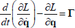
Where Lagrangian is defined as
Defining the variable
The kinetic energy of robot can be given by the following integral

Where


The potential energy of the system is obtained as

By the principle of virtual principle, the general torques matrix is

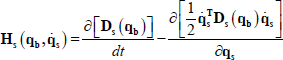
Using Eq. (2), (3) and (4), Lagrange's equation can be written as

Where

And

2.2. Dynamics equation for stance phase
Assuming without slide and rotation under the robot foot, the motion constraint during stance phase is holonomic. The generalized coordinates
According to the Cartesian coordinate space, the COG of robot during stance phase can be denoted as

Hence, the relationship of generalized coordinates between flight phase and stance phase is

Substituting Eq. (7) into (2), the kinetic energy during stance phase yields

Where

Substituting Eq. (8) into Lagrange's equation, yielding

Where

The general torques matrix is

3. Inertia Matching
The concept of inertia matching is widely used in the analysis of actuator and gear systems, primarily for selection of the optimum gear ratio based on the transmission performance between the torque produced at the actuator and the torque applied to the load (D.Z. Chen et al, 1991). In this process, the performance of torque transmission is maximized by setting the optimal balance of inertial properties between the actuator system (including inertia of the rotor and shaft) and the load. The concept of inertia matching for jumping robot is proposed in this paper as a new index of the dynamic performance. The proposed inertia matching ellipsoid characterizes the dynamic torque-force transmission efficiency between joint actuators and a load held by the end-effector of a manipulator, encompassing a wide range of previous concepts.
3.1. Inertia Matching for geared mechanism
Figure 3 shows a one DOF geared mechanism, the equation of motion is

Where

Geared Mechanism
Eq. (10) can be written as

Assuming that

The relation between output shaft accelaeration and gear ratio
It is clear that there exists an optimum gear ratio which yields a maximum output acceleration. At the optimum design, the output acceleration and the gear ratio are given by

By choosing the optimal ratio by Eq. (12), a large acceleration of the load is produced with small output torque at the actuator. It can be said that the gear ratio is chosen such that the reflected input inertia is matched with the output inertia. That is inertia matching.
3.2. Inertia Matching for jumping robot
The concept of inertia matching can be extended to jumping robot as follows. Humanoid jumping robot can be considered as a redundant manipulator with a load held at the end-effector (R. Kurazume et al, 2004). Fig. 5 shows the jumping robot and inertia matching ellipsoid (IME).

Jumping robot and inertia matching ellipsoid (IME)
The motion and force equation analyzing to the load held at the end-effector can be written as

Where
Defined the load matching

Jumping performance is affected by not any motion control, but also the jumping posture and load capability. Jumping posture affects the attitude during flight phase, and the attitude determines the angular moment for COG of robot. Load matching is an important index which affects jumping performance and reflects the capability of supporting a weight or mass. It also affects the distributing of COG. We hope the robot can bear more loads and jump more height.
If the load mass is unknown, when a external moment and force is applied to the jumping robot, the dynamics equation for stance phase can be written as

Where
The end-effector posture of manipulator

Substituting Eq. (15) and (16) into (14), the torque matrix can be obtained by

Where

Here,
3.3. Inertia Matching manipulability
In Eq. (17), the coefficient matrix
Based on the theory of singular value decomposition,

Where
The manipulability measure

The principal axes are the product between the row vector
Generally, the torque limits at each actuator in jumping robot are assumed to be symmetrical and constrained, viz.

Therefore, when a normalized torque with magnitude of 1 is produced, the inertia matching ellipsoid can be obtained as

3.4. Directional manipulability for Inertia Matching
Inertia matching is a vector, it includes a value and direction. However, the inertia matching manipulability
Assuming the moment and force vector applied to the center of load at end-effector is given by

Where
Substituting Eq. (23) into (17), the following equation can be obtained

The directional manipulability of inertia matching can be given by

The directional manipulability measure of inertia matching
4. The load matching optimization for jumping motion
Jumping robot can be considered as a redundant manipulator with a load held at the end-effector. The link is rotary joint between end load and manipulator. This model or equivalent is a valid analysis method to mathematic modeling of jumping robot. In this paper, we consider the jumping height as the main jumping performance.
Analyzing the jumping robot as a whole, we can find that the velocity at take-off determines the jumping height, and the COG trajectory after take-off is a parabola. The take-off motion can be regarded as a process from the initial posture
4.1. The optimization of load matching
From the constraint condition of stance phase, viz. Eq. (6), the acceleration of COG can be written as

The time integral of ground reaction force

Where
The manipulability measure of inertia matching is a function of posture

Where the constraint condition
4.2. The motion plan for jumping motion
In this paper, we plan the jumping motion trajectory during stance phase and flight phase respectively. The jumping motion in planar can be decoupled into the movement in vertical and horizontal direction. During the jumping movement, the COG has a time sequence from

During flight phase, the COG trajectory is a parabola, and it can be obtained by

5. Simulation and experiment
To verify the feasibility of the dynamics model and suggested optimal scheme, we designed a 4- DOF rotary joints and five rigid bodies jumping robot (foot, crus, thigh, trunk and arm). Fig.6 shows our experimental device and jumping robot. The jumping robot can jump in a circle. The horizontal bar of device is attached at the robot's body. The bar providers only lateral stability, and it does not prevent the robot falling forward, backward or down. Every joint of jumping robot is independently driven by servo motor. The type of servo motors is Tower Pro MG995, which made in Taiwan of China. Its rated velocity is

Experimental device and jumping robot. (a) Experimental device for jumping motion. (b) Jumping robot driven by servo motor.

Inertia matching ellipsoid, inertia matching, jumping height and ground reaction force from different load matching. (a) Inertia matching ellipsoid of vertical jumping at different load matching. (b) Inertia matching of vertical jumping at different load matching. (c) Jumping height at different load matching. (d) Ground reaction force at different load matching.
In this paper, the simulation parameters are only related to physical parameters of foot, crus, thigh and load. So, we give those physical parameters as follows

Jumping robot can reach the maximal height by experiments when
The following is the simulation figures. Fig.7 shows inertia matching ellipsoid, inertia matching, jumping height and ground reaction force from different load matching. Fig.8 shows the trajectory for angular angle, angular velocity and angular torque under the optimal jumping performance and load matching.
The numerical simulation shows inertia matching is in direct proportion to jumping height. The inertia matching reach a maximization when
The error percent of load matching between simulation value

The angular trajectory under the optimal jumping performance and load matching. (a) The trajectory of angular angle under the optimal jumping performance. (b) The trajectory of angular velocity under the optimal jumping performance. (c) The trajectory of angular torque under the optimal jumping performance.
6. Conclusions
In this work, the unified dynamics of stance and flight phase for humanoid jumping robot is established based on various constraint conditions and floated-basis space. An effective strategy for optimizing humanoid jumping motion is introduced. The concept of inertia matching is introducing to optimization of humanoid jumping robot. Load matching is an important index which affects jumping performance and reflects the capability of supporting a weight or mass. It also affects the distributing of COG. The load matching for jumping robot is optimized by inertia matching and directional manipulability. Moreover, a 5th order polynomial function is defined to plan the COG trajectory of jumping motion taking into account the constraint conditions of velocity and acceleration, and moreover the trajectory during flight phase is obtained. Numerical simulation and experimental results show the time integral of ground reaction force and jumping height are at the maximization when inertia matching reaches to the optimization. Furthermore, inertia matching is in direct proportion to jumping performance, and inertia matching is a valid optimization method to load matching of jumping motion. The jumping performance includes jumping height and landing stability. In the future, we would like to apply multi-objective optimization to jumping motion plan, such as the functions of objective jumping parameters, jumping height and stability strategy.